

Fluid guidance systems for turbines
A guidance system and turbine technology, applied in the application of control systems, control of reaction engines, wind turbines, etc., can solve the problems of power voltage fluctuation, slow adjustment of hydraulic drive spacing, thick blades, etc., and achieve the effect of stabilizing the rotor speed.
Inactive Publication Date: 2011-12-07
ORGANOWORLD
View PDF9 Cites 23 Cited by
- Summary
- Abstract
- Description
- Claims
- Application Information
AI Technical Summary
Problems solved by technology
Method used
View moreImage
Smart ImageViewing Examples

Examples
example 1
[0138] Example 1: 4.0m / s HAWT segmented rotor
[0139] At 4.0m / s, the segment ratio varies between 1.0 and 0.25. The power generated increases from 10kW to 55kW, or a 5.5-fold increase.
example 2
[0140] Example 2: 7.0m / s HAWT segmented rotor
[0141] At 7.0m / s, the segment ratio varies between 1.0 and 0.25. The power generated increases from 30kW to 300kW, or a 10-fold increase.
example 3
[0142] Example 3: HAWT Segmented Rotor at 12.0m / s
[0143] At 12.0m / s, the segment ratio varies between 1.0 and 0.25. Electricity generated increases from 190kW to 1500kW, or a 7.7-fold increase.
Login to View More PUM
 Abstract
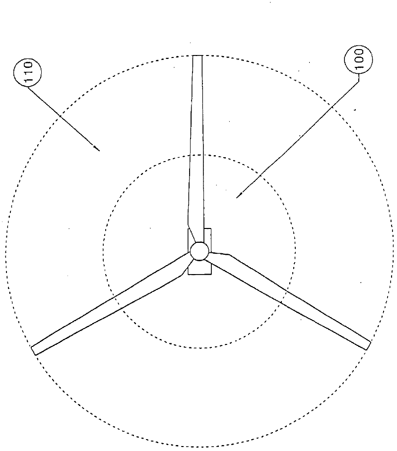
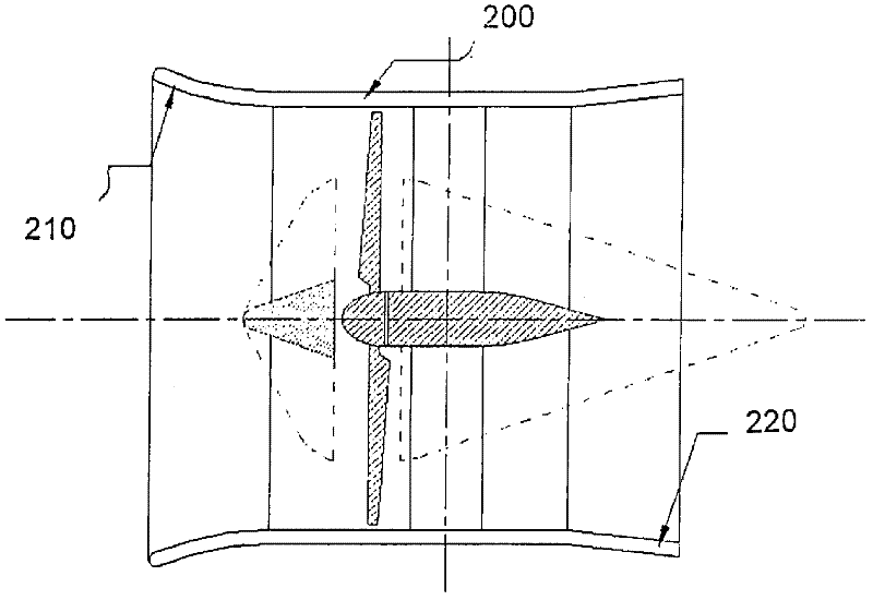
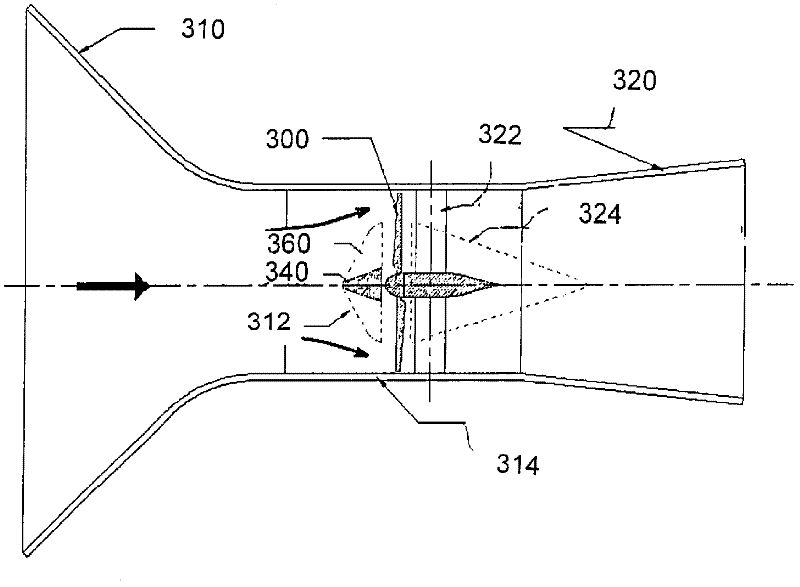
A directing system for directing fluid entering an axial flow turbine along an inlet flow direction. The turbine includes a plurality of turbine blades. The directing system includes a base structure, a plurality of directing segments attached to the base structure, downstream of the base structure, and a directing segment adjustment system for adjustably positioning the directing segments between a retracted configuration and a deployed configuration. The directing segments, in the deployed configuration, extend beyond the base structure in a direction transversal to the inlet flow direction and deflect the fluid towards an outer circumference of the plurality of turbine blades corresponding to a higher torque area of the blades. A directing system for directing fluid entering a cross-flow turbine is also disclosed. In the cross-flow turbine, the fluid is directed towards a centerline of the rotor of the turbine, which is a high torque area of the turbine blades.
Description
technical field [0001] The present invention generally relates to wind turbines and water turbines. More specifically, the present invention relates to a fluid guiding system for guiding fluid entering an axial or cross flow turbine. Background technique [0002] A wind turbine is typically at a wind speed at which the wind turbine produces the rated power of the generator, or substantially the maximum rated power. At low wind speeds, the turbine will only produce a fraction of its rated power. [0003] A weak wind contains less energy than a strong wind, so that the weak wind automatically produces less useful energy. As the Reynolds number of the blades decreases at low wind speeds, the rotor efficiency or percentage of energy converted from the wind into useful torque also decreases. There is a clear need for a rotor design that can increase the power harvested from the airflow at all speeds and especially at speeds below the rated speed of the turbine. Once the rated...
Claims
Login to View More Application Information
Patent Timeline
 Patent Type & AuthorityApplications(China)
IPC IPC(8): F03D1/04F03B11/02F03B15/00F03B3/18F03D1/06F03D7/00
CPCF05B2240/244F05B2210/16Y02E10/72F05B2270/1014F03D1/04F03B15/08F05B2240/211F05B2270/32Y02E10/721F03B17/062F05B2240/221F05B2240/217F05B2240/121Y02E10/226Y02E10/223Y02E10/28F03B3/183F03B17/061Y02E10/20
Inventor弗雷德里克·邱吉尔艾昂·帕拉斯基沃尤奥塔维安·特里富
OwnerORGANOWORLD