High-speed jet gas-liquid mixing-phase ejector

A technology of gas-liquid mixing and high-speed injection, which is applied in the direction of injection devices, liquid injection devices, etc., can solve the problems of low outlet velocity and insufficient penetration depth, and achieve the effect of high liquid flow velocity and weakened boundary layer effect

Inactive Publication Date: 2009-07-29
ZHEJIANG UNIV +1
View PDF0 Cites 31 Cited by
  • Summary
  • Abstract
  • Description
  • Claims
  • Application Information

AI Technical Summary

Problems solved by technology

[0004] In order to solve the problems of low outlet velocity and insufficient penetration depth in existing atomizing nozzles or injectors, the present invention provides a high-speed spraying gas-liquid mixed-phase injector

Method used


Image

  • High-speed jet gas-liquid mixing-phase ejector
  • High-speed jet gas-liquid mixing-phase ejector
  • High-speed jet gas-liquid mixing-phase ejector

Examples


specific Embodiment example 1

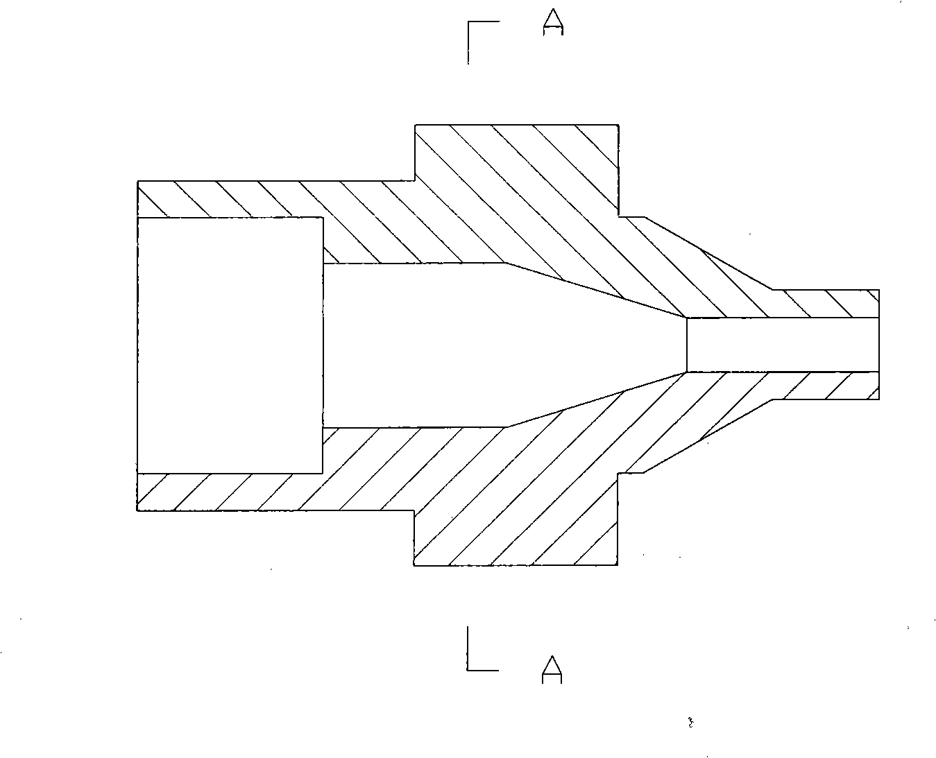
[0031] The gas-liquid mixed-phase injector for high-speed injection in this embodiment is made of 304 stainless steel, and includes a liquid phase inlet pipe 1 and a gas phase inlet pipe 2 with quick fittings respectively. The end of the liquid phase inlet pipe 1 is connected to the liquid phase Nozzle 3, the end of the gas phase inlet pipe 2 is connected to the gas phase nozzle 4; the gas phase inlet pipe 2 surrounds the outside of the liquid phase inlet pipe 1 and forms an annular gas phase flow channel, and the gas phase nozzle 4 surrounds the outside of the liquid phase nozzle 3 and connects the mixing The phase channel 5 and the end of the mixed phase channel 5 are connected to the outlet nozzle 6 .

[0032] The liquid-phase inlet pipe 1 and the gas-phase inlet pipe 2 are respectively connected to a source of ammonia solution with a concentration of about 10% and a source of compressed air through a threaded quick-fit joint. The liquid phase inlet pipe 1 is welded to the ...

specific Embodiment example 2

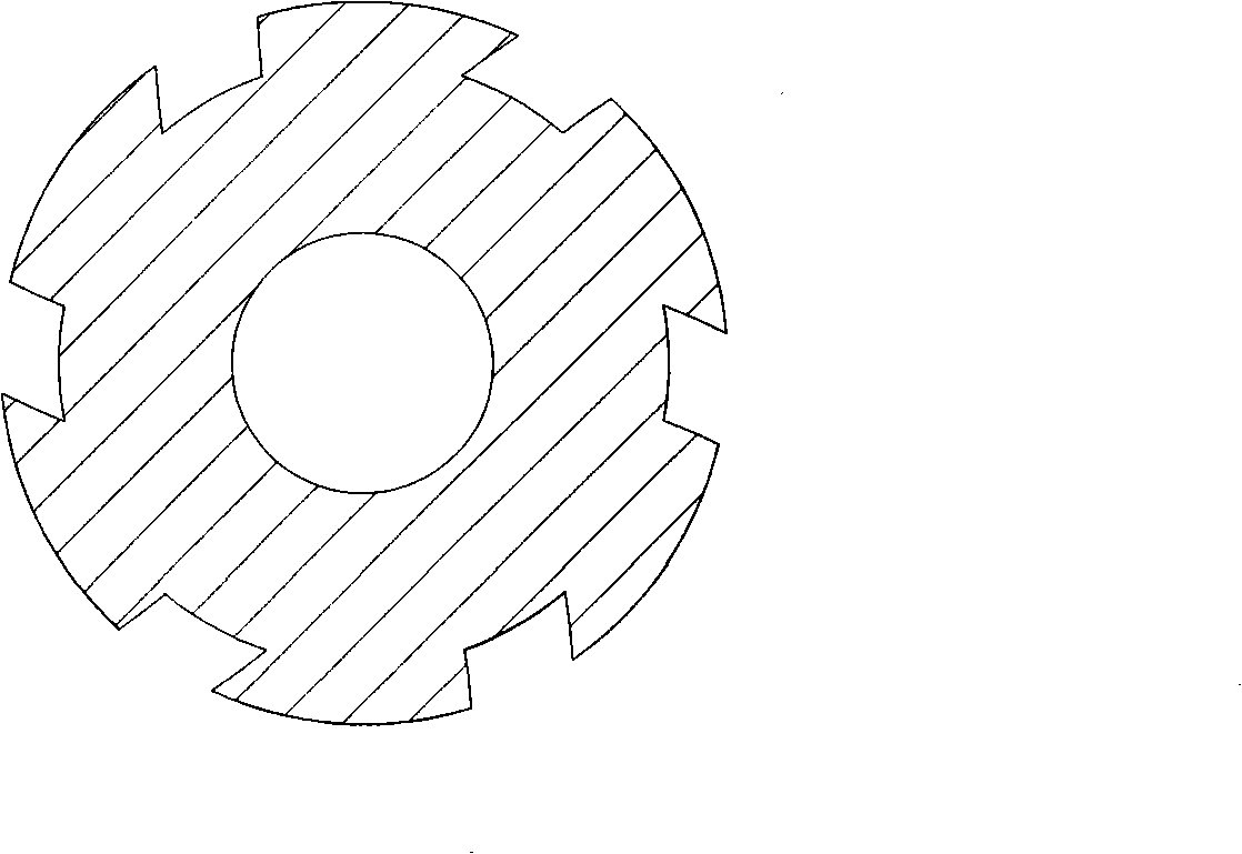
[0035] Different from Embodiment 1, the outlet nozzle 6 of the gas-liquid mixed-phase injector for high-speed injection in this embodiment is provided with 3 outlet holes of equal size, the included angle of the axes is 30°, and the gas-phase swirl sheet is arranged outside the liquid-phase nozzle 3 7. The swirl blade angle is 30°.

[0036] The liquid phase inlet pipe 1 and the gas phase inlet pipe 2 are respectively connected to a urea solution source with a concentration of about 10% and a superheated steam source through a threaded quick-fit joint. The liquid phase inlet pipe 1 is welded to the liquid phase nozzle 3, the gas phase inlet pipe 2 is welded to the gas phase nozzle 4, the gas phase nozzle 4 is welded to the mixed phase flow channel 5, and the outlet nozzle 6 is connected to the mixed phase flow channel 5 with sealing threads.

[0037] The working process of the injector of the present invention is as follows: the urea solution source with a concentration of abou...


PUM


Abstract

The invention relates to a fluid ejector, and aims to provide a gas-liquid mixed phase ejector for ejecting at a high speed. The ejector comprises a liquid phase inlet pipe and a gas phase inlet pipe which are provided with a quick coupler respectively; the tail end of the liquid phase inlet pipe is connected with a liquid phase nozzle; the tail end of the gas phase inlet pipe is connected with a gas phase nozzle; the liquid phase nozzle is a single-hole nozzle; a flow passage from the liquid phase inlet pipe to the liquid phase nozzle has smooth transition; the gas phase inlet pipe encloses the outside of the liquid phase inlet pipe to form an annular gas phase flow passage; the gas phase nozzle encloses the outside of the liquid phase nozzle and is connected with a mixed phase flow passage; the tail end of the mixed phase flow passage is connected with an outlet nozzle; and an outlet circulation sectional area of the outlet nozzle is smaller than that of a circulation sectional area of the mixed phase flow passage. The liquid phase nozzle has high-speed outlet liquid flow, and the high-speed outlet liquid flow is interacted with high-speed gas phase flow in the mixed phase flow passage to realize atomization and once more acceleration, thereby the ejector greatly weakens boundary layer effect on the outlet, avoids that liquid drops separating from main jet flow are convergent to drop on the outlet, and can flexibly adjust and control atomization fineness and distribution.

Description

technical field [0001] The invention relates to a fluid injector, more specifically, a gas-liquid mixed-phase injector for high-speed injection, which belongs to fluid atomization injection equipment. Background technique [0002] In the process of industrial production and environmental protection control, it is often encountered that small flow fluids are sprayed into large flow fluids and mixed with each other. In this type of problem, due to the small flow rate and the limited injection position, the small flow fluid can only be partially mixed with the large flow fluid or the required mixing time is too long. Such problems arise when boilers employ selective non-catalytic reduction technology for NOx control, where reducing agents are injected into the flue gas. For this kind of problem, it can not be completely solved by atomizing the small flow liquid fluid into small particles or increasing the swirl degree of the jet. It has unique requirements for the atomization ...

Claims


Application Information

Patent Timeline
Patent Type & Authority Applications(China)
IPC IPC(8): B05B7/04B05B7/06
Inventor 周俊虎岑可法杨卫娟黄镇宇刘建忠王智化周志军程军
Owner ZHEJIANG UNIV
Why Eureka
Try Eureka