System and method for extracting power from fluid using a Tesla-type bladeless turbine

a technology of bladeless turbines and fluids, applied in the direction of liquid fuel engines, renewable energy generation, greenhouse gas reduction, etc., to achieve optimal longitudinal spacing, minimize losses, and increase efficiency

Inactive Publication Date: 2014-08-12
SHERRER GORDON DAVID
View PDF49 Cites 27 Cited by
  • Summary
  • Abstract
  • Description
  • Claims
  • Application Information

AI Technical Summary

Benefits of technology

[0018]An object of the present invention is to provide a system and method for extracting power from fluids in motion. In accordance with an aspect of the present invention, there is provided a fluid powered work generating system comprising: one or more disc turbines each having an inlet and an outlet, said one or more disc turbines configured to advantageously interact with motive fluids for work generation by providing inter-disc spacing between adjacent disc elements advantageously respecting fluid kinetic viscosity and rotor angular velocity; a fluid collection device configured to increase the velocity of fluid currents passing through swept regions, the fluid collection device in fluidic communication with the inlet, the fluid collection device configured to capture a substantial portion of the fluid prior to providing the portion of the fluid at one or more inlets; and a fluid extraction device in fluidic communication with the outlet, the fluid extraction device configured to deliver a second portion of fluid, said second portion of fluid being delivered at an advantageous initial pressure and velocity and acting upon one or more outlets through viscous drag, thereby enhancing extraction of the portion of the fluid from the outlet.
[0019]In accordance with another embodiment of the present invention, there is provided a method for generating power from fluids in motion, said method comprising the steps of: intersecting a cross-section of moving fluid with smooth, inclined and or cambered, rectangular or other prismatic or revolved open or closed-form fluid collection device surfaces developing thick sheet-like, or venturi-like fluid flow there-over or there-through of enhanced velocity compared to the ambient fluid velocity; and capturing a portion of the enhanced velocity near surface fluid flow conducted there-across said fluid collection device surface; and directing said provided portion of the fluid at an advantageous angle of attack toward partial admission, or directing multiple or thicker flow cross sections of enhanced velocity fluids toward full admission about the periphery one or more disc turbines, while maintaining parallel relationship between the direction of fluid approach and the planes defined by the surfaces of the discs of the one or more disc turbines; and providing advantageous disc turbine design features, including: disc diameters suited to operation in available fluid current velocities; advantageous inter-disc spacing not less than the optimal disc spacing related to kinetic fluid viscosity and rotor angular velocity; disc shape and texture concerning to laminar flow characteristics; and equipping disc turbine discharges with close-fitting outlet connections diverging with distance there-from; and providing a fluid extraction device configured to deliver a second portion of fluid into fluidic communication with the outlet flow of one or more disc turbines, said second portion of fluid being delivered at an advantageous pressure and velocity and in leeward facing alignment with holes conducting disc turbine outlet flow such that the one or more discharge outlets of the one or more disc turbines are acted upon by significant viscous drag and entrainment capacity, thereby enhancing extraction of the portion of the fluid from the outlets; wherein said disc turbine or disc turbines interact with the fluid thereby generating power.
[0020]In accordance with another embodiment of the presently disclosed invention, there is provided a means with which to effect variable cross-sectional area fluid intersection by the fluid collection device, as well as control thereof, to •enhance the energy made available for extraction by disc turbines of the method from given ‘swept areas’ of ambient fluid currents, whereby the fluid collection device may include an automatic means for achieving the desired fluid cross-section intersect and resultant enhanced fluid velocity control effects at run-time, through the employment of: one or more actuators such as piston actuators attached to opposite hulls of preferably mirror image halves of a given device embodiment; further provided a preferably analog control signal or pressurized control fluid in response to; fluid speed information received from a dynamic pressure indicating device such as a pitot tube positioned in the flow-stream which may be readily provided to; a programmable logic controller (PLC) or other independent feedback-loop controller with PID loop control capability able to respond quickly in rapidly fluctuating conditions, to compare and calculate a new position-respecting control signal, further; received by positioning-capable actuators, or intermediary transducing elements further conveying said control signal or control fluid to actuators to cause the required extension or retraction in response to controller-issued commands as required, which may for instance, cause extension upon decreasing dynamic pressure inputs, and or retraction upon increasing dynamic pressure inputs so as to maintain controlled height positioning, disposed cross-sectional fluid intersection, and achieve a steady or enhanced fluid velocity and structural loading condition under changing ambient fluid conditions. Notably, controllers with adaptive gain and or fuzzy logic may prove advantageous in such applications where learned tendencies in fluid current patterns may be repeatable to a degree.

Problems solved by technology

It is appreciable, however, that while appendages responsible for developing rotation may be designed to render minimized flow obstruction and may advantageously induce airfoil (or hydrofoil) speed beneficiation, a sizeable component of the working fluid's kinetic energy is nevertheless rendered unavailable for work conversion by such machines due to losses owing to: the shock of fluid impingement upon appendages exposed to the moving fluid streams, and the resultant re direction and eddying of fluid molecules resulting from the process of driving certain prior art rotors at 90° to the applied fluid currents for at least part of their cycle; the ‘swirl’ effect caused by fluid discharging tangentially and in some cases radially from bladed or annular rotors due to surface adhesion and centrifugal forces acting over the rotating blade profile contributing to the development of wasteful down-stream vortices; all components working to produce a disadvantageous backpressure effect tending to resist the forward momentum of subsequent fluid flow though the same cross-section.
Unfortunately and typically, this involves the diversion of significant water resources into pen-stocks bound for points of generation some distance away, which invites ecological concern due to its considerable effect upon the habitat of aquatic life, a consequence that true RISEC applications may avoid.
While prior art in the emerging field of tidal in-stream energy conversion (TISEC) harvests clean energy from seawater in motion, these typically bladed devices present danger of injury to aquatic life which may be driven under powerful tidal or oceanic currents unto impact with rotating blades disposing moving obstacles in the path of indigenous aquatic creatures.
Whereas skirt augmenters (5) may be employed to develop venturi-like pressure reduction behind bladed rotors housed within the skirts to increase rotor speeds and extractable power output with the generation of greater flow-rates there-through, these devices may concurrently increase the risk of more serious injury to aquatic life through the speed increases sought, especially at the blade extremities.
Whereas collectors in the method provide added energy to turbines for conversion, these types of turbines suffer losses similar to those already described in respect to bladed turbines, and no means is provided for discharging into lower than ambient pressure fluid streams to increase the efficiency of the method.
The advantages disclosed by Finney (9) for use in various fluids including air and water further providing dramatic velocity and power increases in working mediums at length applied to axial turbines located adjacent the throat of serially staged venturis of sequentially larger cross-sections are significant, however, are also subject to energy losses described through their utilization of bladed turbines.
While Bosley (11) offers inherently minimized electrical generation losses leading to less heat loading of waters surrounding TISEC devices, even with the optionally proposed flow-enhancing shroud, the annular rotor comprising a plurality of paddles introduces bladed art deficiencies already discussed, and no impeller improvements are suggested to improve rotor speeds for greater conversion gains.
However, the drag coefficient utilized while limiting to cavitation permits significant energy escape in the fluid reintroduced to the ambient tidal flow resulting in lateral displacement thereof in a common direction potentially changing the sedimentation patterns at depth further affecting marine life habitats.
The wind-turbine of Stanton (14) suggests form-induced air acceleration with a funnel shaped concentrator and axial bladed turbine to harvest energy from the added pressure differential obtained via discharge of energized turbine throughput into a lower pressure region in the lee of the proposed collector, however, Stanton's method is also subject to the disadvantages described regarding bladed turbine losses, and similarly does not expound upon an advantageous method to further reduce downstream discharge back-pressures.
Also, this method neither suggests nor enables service in non-compressible fluid environments as the 5% outlet to inlet cross-section disclosed would tend to stagnate the bulk of the fluid mass in water applications.
Bladed horizontal axis wind turbines and arrays thereof, generally thought to comprise modern-day wind-farms typically provide increased power benefit through installation in high wind areas, however, these areas may be coincident with fly-zones and / or nesting grounds of eagles, falcons and other endangered bird species put at risk of injurious collision with the moving rotors of such machines.
Technologically assuming great proportion in part to overcome anticipated, previously described losses observed, bladed prior art spinning faster in high ground areas put birds of flight at increased risk of consequence.
Further, the aesthetics of visual and sonic impacts in residential and other areas currently limit the extent to which wind energy harvest as it is known today is utilized.
While offering large fluid collection surface areas and low ambient work generation fluid cut-in speeds, and rotors utilizing the Magnus effect for positional stability, they may otherwise adversely present obstacles for aviators, the power extraction capacity offered therein are nevertheless lower than bladed wind turbines.
While affording speed beneficiation of approaching wind via the convergent-divergent external guiding means disclosed, the disposition of internal disc-separating helical surface appendages provided may otherwise limit the efficiency of the disc turbine internally employed, since to provide best effect, working fluid in disc turbines should be free to travel in natural streamlines of least resistance (1) to maintain laminar flow between co-rotating discs.
Whereas this may require that working fluid complete possibly many revolutions between disc surfaces for optimal effect, this requirement is largely prevented in the method by the inter-disc ribs forcing working fluid to follow multiple pre-designated trajectories each potentially introducing turbulence between discs and efficiency losses accordingly.
In general, issues such as low frequency noise from rotating blades slicing through gaseous and liquid fluids, cavitation of liquid fluids into gaseous fluid inclusions disrupting laminar flows across work generation surfaces further affecting both noise levels and power outputs alike in underwater turbines, and the general lack of machines able to engage greater fluid cross sections in work generation and or conversion currently limits the timely maximization of energy returns from machines of the prior art.

Method used


Image

  • System and method for extracting power from fluid using a Tesla-type bladeless turbine
  • System and method for extracting power from fluid using a Tesla-type bladeless turbine
  • System and method for extracting power from fluid using a Tesla-type bladeless turbine

Examples


embodiment 401

[0176]Meanwhile, wind entering into first convergent section of external shroud 406 and following the path indicated by arrows 420, upon reaching the divergent section 462 of shroud 406 is directed away from the axis of discharge by diverging profile and upon doing so generates a high velocity discharge stream 425 acting to entrain the internal turbine exhaust stream at 440, placing the discharge air 430 from the divergent section of the disc-turbine exhaust channel 409 substantially within divergent section 462, thereby beneficiating the differential pressure across the disc-turbine systems embodiment 401, the speed of its shaft 471 rotation, and the resultant electrical work output realized from its co-rotating alternator. As shown, post-entrainment of the turbine exhaust stream into the high velocity diverging low-pressure fluid extraction device shroud flow, the total air-stream 441 resumes traveling with the local wind-mass at a speed substantially the same as the native wind, ...

embodiment 701

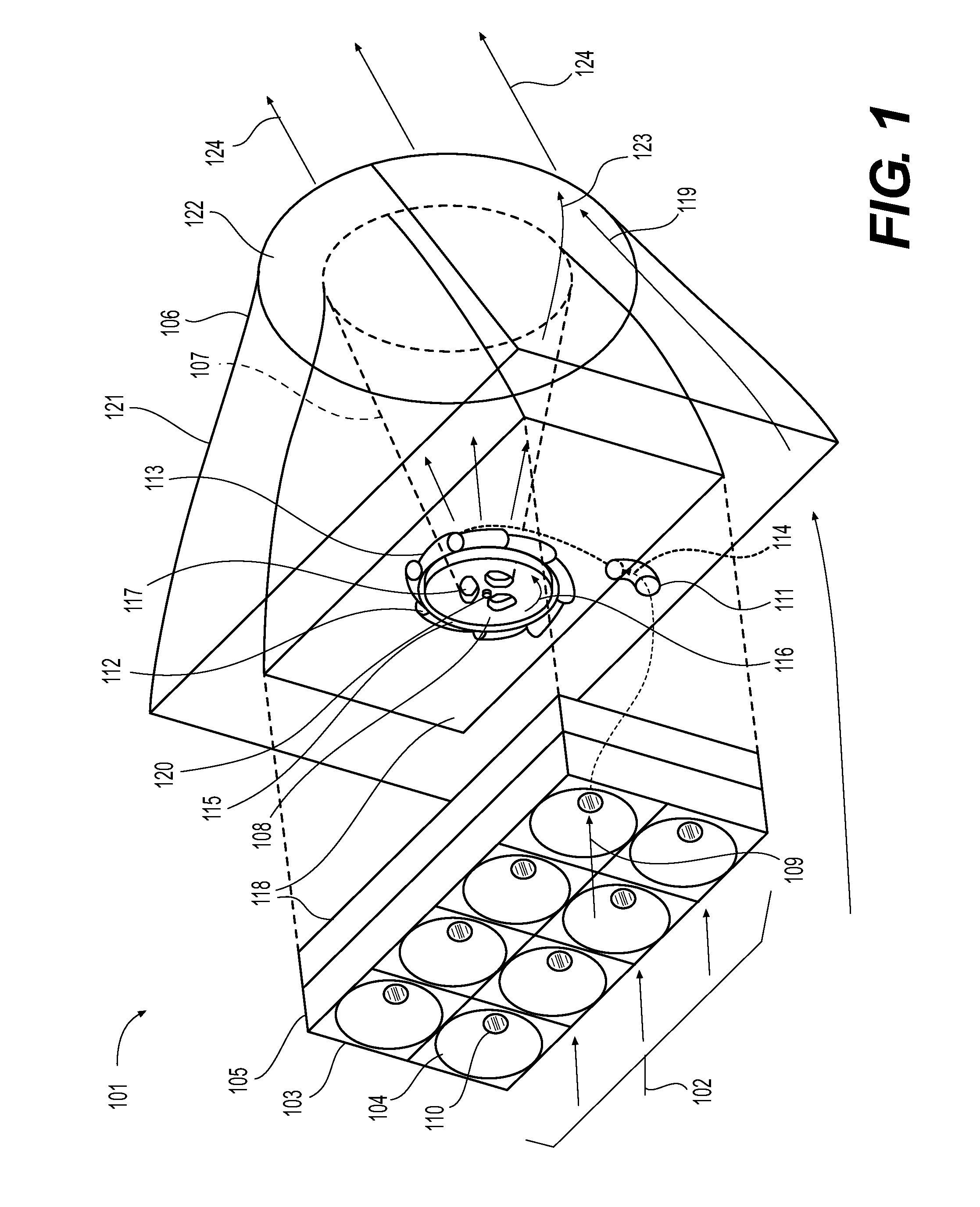
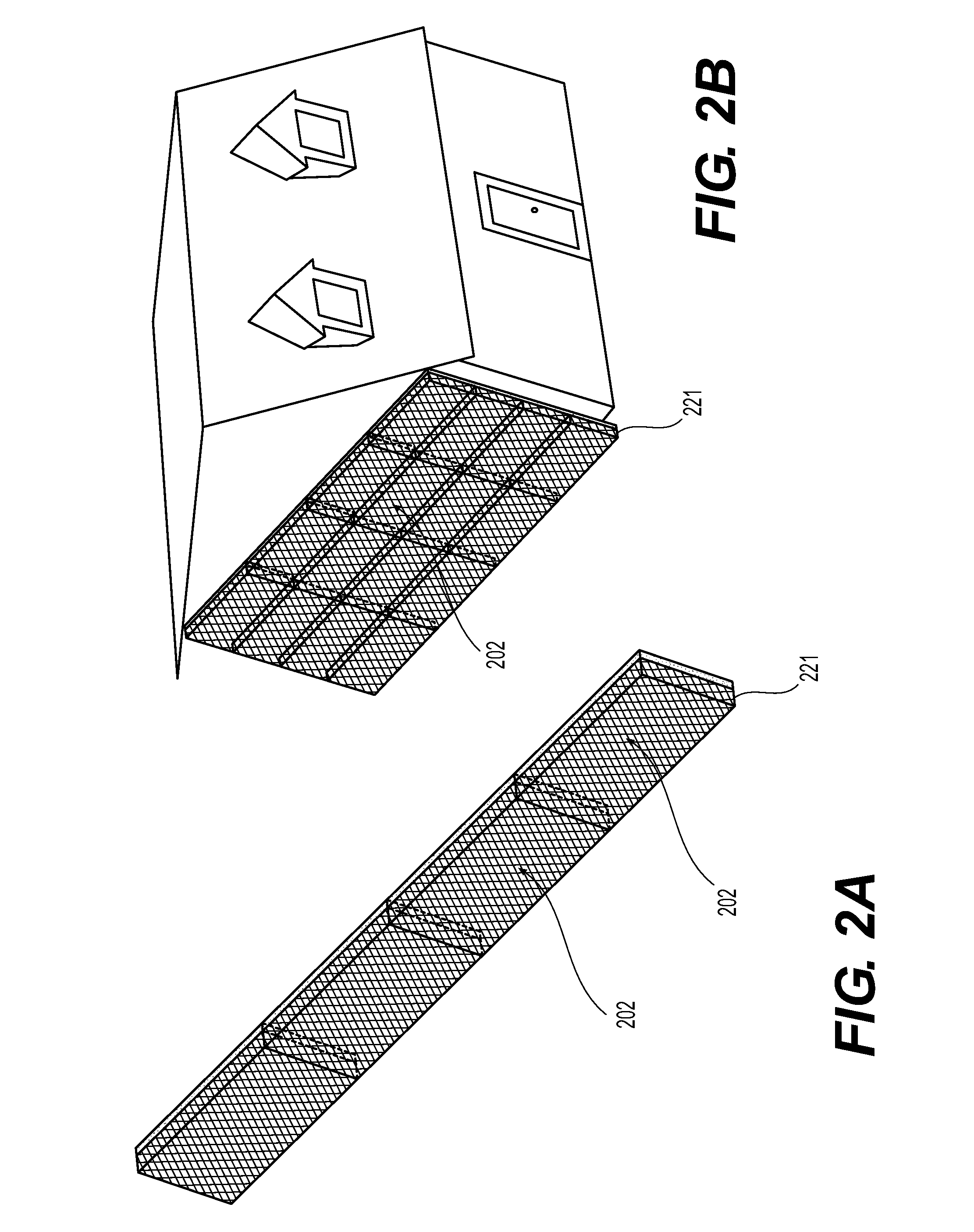
[0185]As indicated in the figure, embodiment 701 disposed in the path of ambient fluid currents 702 permits fluid flows 706 and 704 to enter into convergent upper and lower fluid collection devices (FCD) 705 and 703, and also permits fluid flow externally around device 721. Choosing flow 706 in FCD 705 first, ambient fluid 702 may be driven between converging upper and lower surfaces of FCD 705 laterally bounded by fluid inlet wall 709 developing a combined EVFES 710 as flow 706 merges toward the smaller end of FCD 705, with said EVFES 710 thus developed either passing via involute fluid inlet(s) 711 unto tangency and entry there-into work extracting disc turbines 712, or alternately passing through ‘blow-through slots’720 comprising openings to produce discharge flows 719.

[0186]The disc turbines 712 have isolation end plates 713 secured and having central hole(s) matching disc turbine axial discharge hole(s) pattern. Isolation end plates 713 isolate the fluid flow within the volute...

embodiment 1101

[0200]As shown in the figure, embodiment 1101 integrates the invention concept into the shell of a building aligned so as to intersect the mean wind-flow pattern through the region. Ambient wind currents 1102 intersected by the large building face surfaces 1104 though inclining nevertheless represent a very large surface area disposed to the vector of said fluid currents' approach and thereby develop into an EVFES 1103. EVFES 1103, driven substantially along the azimuth of the ambient wind vector unto tangency with work extracting disc turbines 1106 mounted for rotation at the mouth of involute fluid inlet(s), or volute(s), integrated into the shell of said building face 1104 may develop initial rotation of said disc turbine(s). Medians 1105 may serve to direct added working fluid to each involute fluid inlet so as to guide EVFES arriving from alternate azimuths into alignment disc turbines. EVFES not entering turbine(s) 1106 and driven over the roof-top to become fluid extraction d...


PUM


Abstract

Smooth, preferably variable-sweep fluid collection device surfaces disposed into opposition with wind, river, surf, ocean or tidal currents generate enhanced velocity fluid flows at length driven into onboard work-extracting disc turbines at advantageous angles of attack. Keyed to shafts turning freely through optionally extendable volutes, disc turbines comprising a dense population of smooth, axially fixed or adjustably spaced discs conducting preferably laminar flow between adjacent elements develop significant torque through boundary layer adhesion and viscous shear-stress between fluid layers. Exhaust of disc turbine throughput into divergent channels drafting into external currents of initially higher than ambient velocity and lower pressure may reduce turbine discharge backpressure, rapidly clear system throughput, and allow normally disadvantageous drag to be utilized to develop greater work generation. Gainfully turning with, instead of at odds to natural or anthropogenic currents provided, disc turbines utilized as disclosed may provide unprecedented renewable energy from fluids in motion.

Description

FIELD OF THE INVENTION[0001]This invention relates to the field of machines extracting and converting energy from fluid currents in motion, and in particular, it relates to a method and systems for efficiently converting the kinetic energy of preferably large cross-sectional areas of wind, river, surf, ocean and tidal flows into clean, zero emission, electric, hydraulic, mechanical or alternate work outputs utilizing ecologically preferable machines offering great power per weight in superficially motionless and substantially quiet packages.BACKGROUND[0002]In prior art machines which harvest the power of fluids in motion it is common practice to employ a rotor upon which are affixed, milled or moulded variously formed blades, buckets, paddles, vanes or other such appendages so pitched thereupon that when subjected to a fluid current, continuous molecular impingements, foiling and eddying interactions between the fluid-mass supplied and the commonly pitched appendages results in rota...

Claims


Application Information

Patent Timeline
Patent Type & Authority Patents(United States)
IPC IPC(8): F03D3/00F03B3/18F03B17/06F03D3/04F03D11/02
CPCF03B3/18F03B17/062F03D11/02F03D3/0436F03D3/0427F05B2240/213F05B2240/221F05B2240/911Y02E10/728F05B2240/13F05B2250/713F05B2240/211F05B2240/133F05B2240/40Y02E10/223F05B2250/5011F05B2240/9113Y02E10/74Y02E10/28F03D15/00Y02E70/30F03D3/02F03D15/20F03D9/34Y02E10/20
Inventor SHERRER, GORDON, DAVID
Owner SHERRER GORDON DAVID
Why Eureka
Try Eureka