Encapsulated electronic device and method of manufacturing

a technology of electronic devices and encapsulation, which is applied in the direction of organic semiconductor devices, electroluminescent light sources, electric lighting sources, etc., can solve the problems of known devices still suffering from gradual degradation by moisture, and achieve the effects of reducing the yield of the manufacturing process, facilitating the handling of thin film based devices under construction, and increasing yield

Inactive Publication Date: 2011-07-14
NEDERLANDSE ORG VOOR TOEGEPAST-NATUURWETENSCHAPPELIJK ONDERZOEK (TNO) +1
View PDF17 Cites 37 Cited by
  • Summary
  • Abstract
  • Description
  • Claims
  • Application Information

AI Technical Summary

Benefits of technology

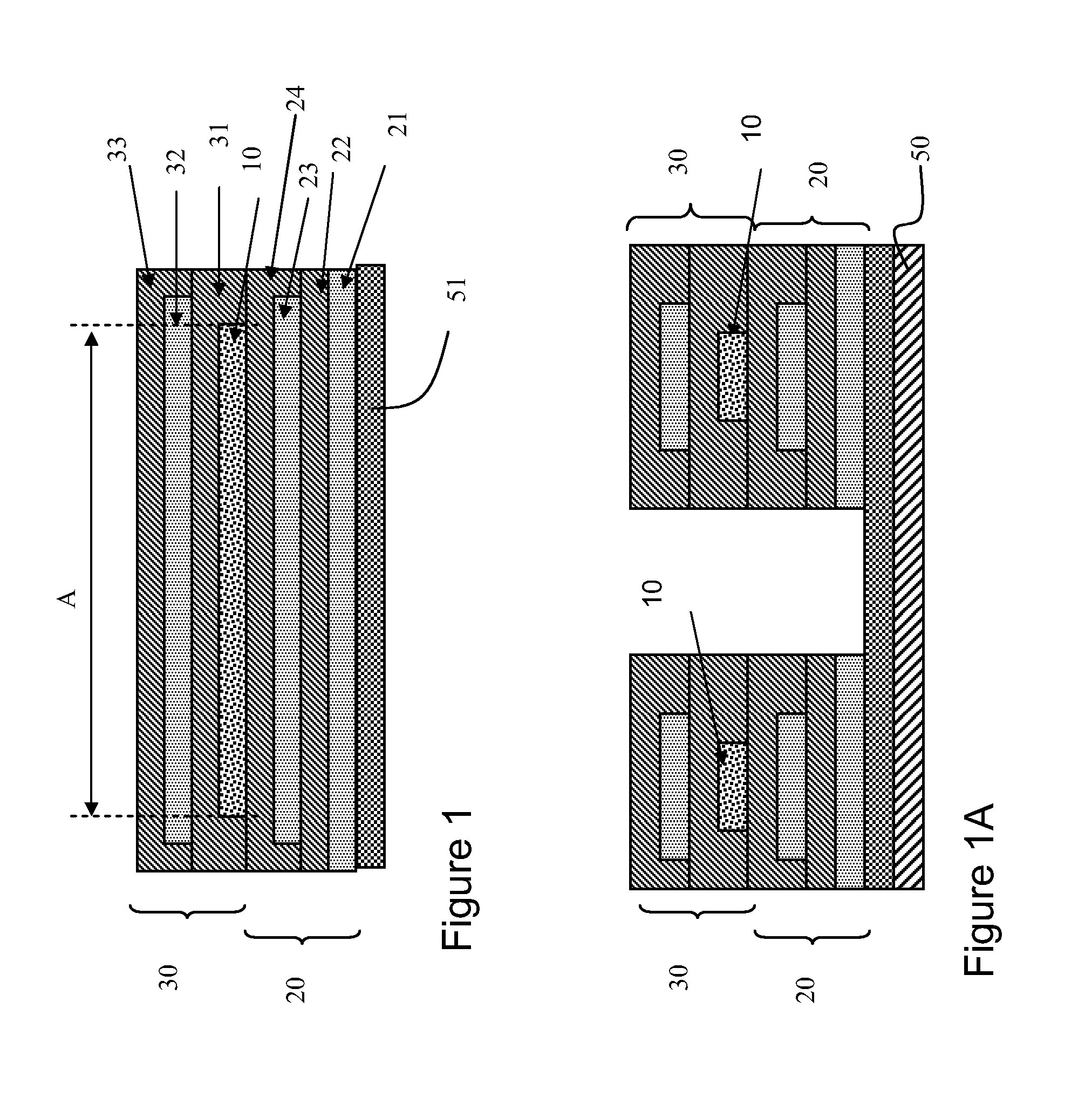
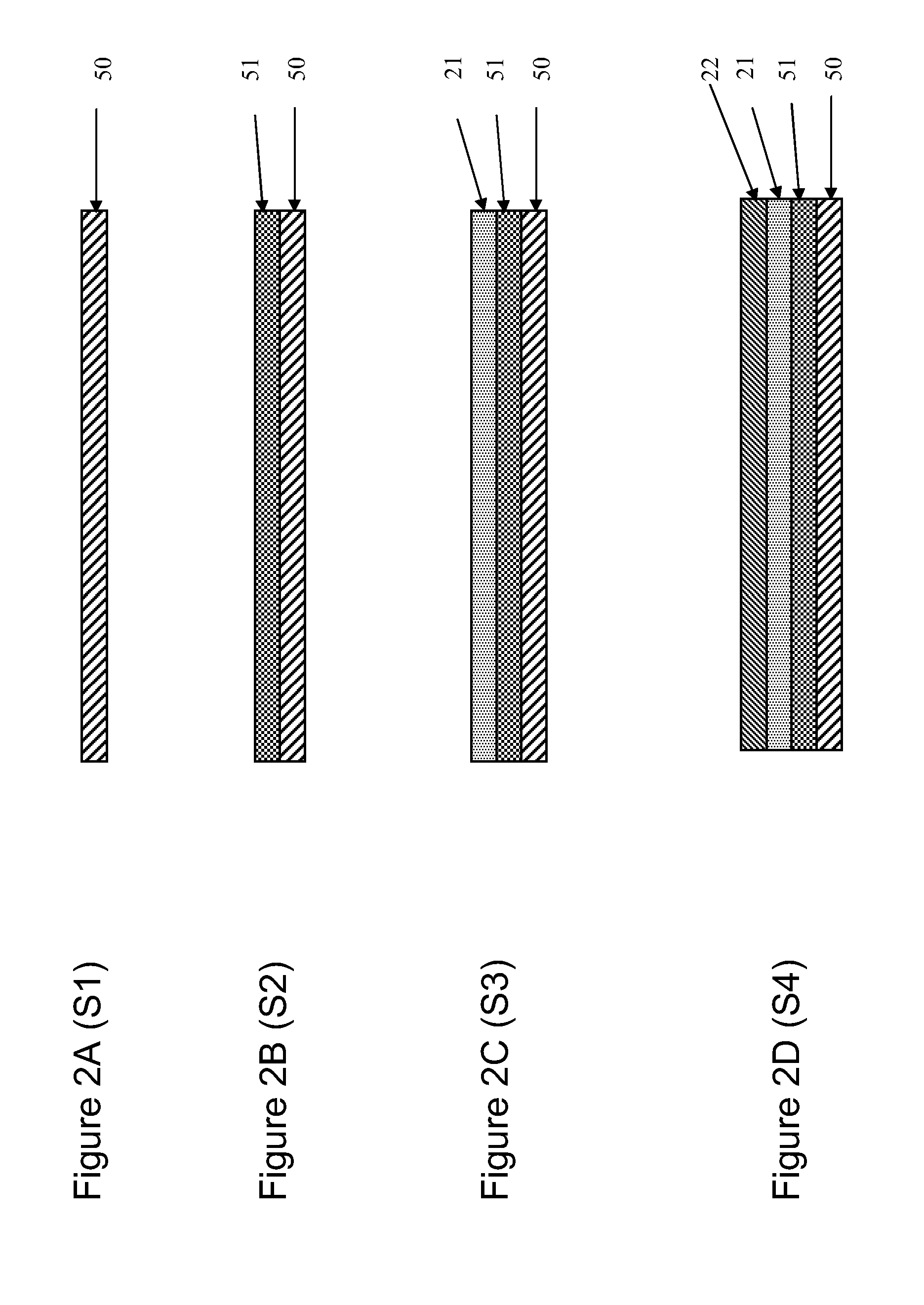
[0026]The substrate facilitates the handling of the thin film based device under construction as it provides stiffness thereto. It is however desirable to remove the substrate at the end, as it is often preferred that the end-product is more flexible. It has, however, been observed that removal of the substrate tended to lead to premature failure of the product and therewith resulted in a decrease of the yield of the manufacturing process. According to a preferred embodiment of the method the encapsulated electronic device is released from the substrate after its completion and the substrate is made of an inorganic material. It was found by the inventors that this embodiment of the method results in an increased yield, as compared to a method wherein a substrate of an organic material is removed from the encapsulated electronic product. It is suspected that this improvement of yield is achieved as the inorganic material attracts dust-particles from the atmosphere less than is the case with organic materials. Dust particles on the substrate tend to cause pinholes in the inorganic layer, resulting in leakage of moisture into the electronic device.
[0027]A preferred embodiment of the method of manufacturing an encapsulated electronic device is characterized in that the substrate or a release layer thereon is patterned. The patterned (corrugated) substrate or the release layer then functions as a template for the first inorganic layer that is applied on the substrate. Corrugation of the device-air interface leads to an improvement of 20 to 40% of the light extraction from the device by reduction of trapping of the light by total internal reflection. By applying the corrugation of the first inorganic layer in this way an improved output efficiency of the encapsulated electronic device is realized without additional manufacturing steps. Furthermore it reduces the number of (reflecting) interfaces between active layer and the outer surface in comparison with a situation where a separate corrugation layer is attached to the surface of the device. Various shapes and sizes of the corrugations are suitable to improve light output e.g., corrugations in the shape of gratings or microlenses both improve the light output from a device to roughly the same extent. It has been established that the corrugation depth is an important factor, a depth of approx. 0.5 micrometer being a typically effective depth for a white emitting device.

Problems solved by technology

Although the construction described in the cited US2001 / 0015620 clearly improves the lifetime of the OLED, it has been observed by the inventors that the known device still suffers from a gradual degradation by moisture.

Method used


Image

  • Encapsulated electronic device and method of manufacturing
  • Encapsulated electronic device and method of manufacturing
  • Encapsulated electronic device and method of manufacturing

Examples


Embodiment Construction

[0037]In the following detailed description numerous specific details are set forth in order to provide a thorough understanding of the present invention. However, it will be understood by one skilled in the art that the present invention may be practiced without these specific details. In other instances, well known methods, procedures, and components have not been described in detail so as not to obscure aspects of the present invention.

[0038]The invention is described more fully hereinafter with reference to the accompanying drawings, in which embodiments of the invention are shown. This invention may, however, be embodied in many different forms and should not be construed as limited to the embodiments set forth herein. Rather, these embodiments are provided so that this disclosure will be thorough and complete, and will fully convey the scope of the invention to those skilled in the art. In the drawings, the size and relative sizes of layers and regions may be exaggerated for c...


PUM


Abstract

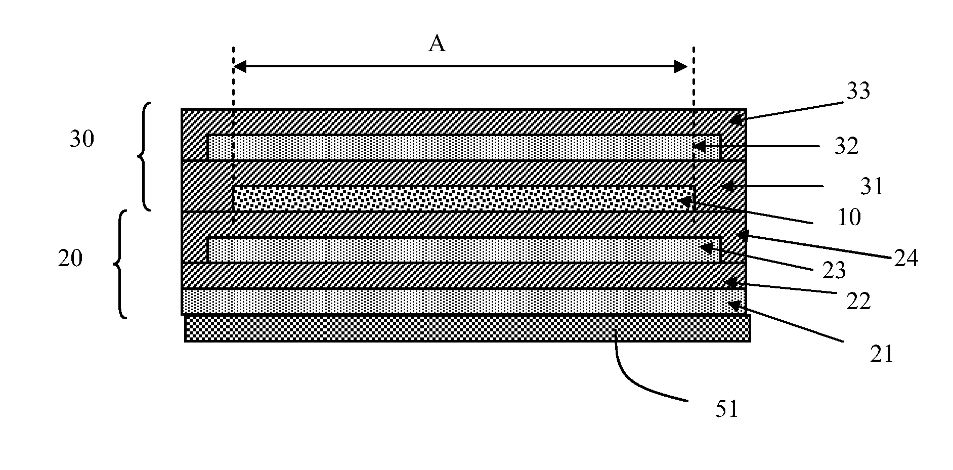
An encapsulated electronic device is described comprising:
    • a first barrier structure (20) comprising at least one inorganic (24) and at least one organic layer (23),
    • a second barrier structure (30) comprising at least one inorganic (31) and at least one organic layer (32),
    • an electronic device (10) arranged between the first and the second barrier structure (20, 30),
characterized in that the at least one inorganic layer (24) of the first barrier structure (20) and the at least one inorganic (31) layer of the second barrier structure (30) contact each outside an area (A) occupied by the electronic device (10).

Description

BACKGROUND OF THE INVENTION[0001]1. Field of the Invention[0002]The present invention relates to an encapsulated electronic device.[0003]The present invention further relates to a method of manufacturing an encapsulated electronic device.[0004]2. Related Art[0005]A new generation of thin film based devices, such as organic light emitting diodes (OLED) for lighting and displays, thin film batteries, thin film organic solar cells, electrochromic foils, electrophoretic displays, etc., have the potential to become a next revolution in electronic systems. These thin film devices have to be protected from contamination by moisture. For that purpose, the last decade several thin film barrier coatings have been developed, often based on a stack of organic and inorganic layers. An example thereof is described in US 2001 / 0015620. The moisture protected thin film based devices described therein comprises a foundation having a top of a first polymer layer, a first ceramic layer on the first pol...

Claims


Application Information

Patent Timeline
Patent Type & Authority Applications(United States)
IPC IPC(8): H01L51/56
CPCB82Y20/00B82Y30/00H01L51/5268H01L51/5275H01L51/003H01L51/5256H01L2251/5369H10K71/80H10K50/8445H10K50/854H10K50/858H10K2102/331H05B33/04H10K50/805
Inventor TOONEN, LEONARDUS MARIARENSING, PETRUSVAN MOL, ANTONIUSLIFKA, HERBERTTANASE, CRISTINA
Owner NEDERLANDSE ORG VOOR TOEGEPAST-NATUURWETENSCHAPPELIJK ONDERZOEK (TNO)
Why Eureka
Try Eureka