Micropump for electronics cooling

a micropump and electronic cooling technology, applied in the direction of positive displacement liquid engine, pump control, pump components, etc., can solve the problems of large electrical power and space needed for the pump, the use of the external pump in the practical application, and the need for an external pump, etc., to achieve the effect of increasing the fluid flow rate and improving the fluid flow ra

Inactive Publication Date: 2010-09-28
PURDUE RES FOUND INC
View PDF13 Cites 26 Cited by
  • Summary
  • Abstract
  • Description
  • Claims
  • Application Information

AI Technical Summary

Benefits of technology

[0006]An illustrative embodiment of the present invention provides a micropump that comprises a plurality of microchannels and a vibrating diaphragm that covers the microchannels. The vibrating diaphragm preferably comprises a piezoelectric actuator to vibrate the diaphragm, although other means for actuating the diaphragm to vibrate such as an electrostatic actuator, electromagnetic actuator, shape memory alloy and others can also be utilized instead of piezoelectric actuation. Electrodes are disposed on the surface of the diaphragm facing the microchannels to provide, when energized, an electrohydrodynamic (EHD) enhancement of fluid flow. Alternately or in addition, the electrodes may be disposed on side and / or bottom surfaces of the microchannels to this same end. The vibration motion on the fluid in combination with the EHD action on the fluid produce a synergistic effect that provides a higher fluid flow rate.
[0007]Another illustrative embodiment of the present invention provides a micropump that comprises a pumping chamber having a pumping diaphragm that alternately increases and decreases the volume of the pumping chamber to move a working fluid through an inlet nozzle-diffuser element in fluid communication with the pumping chamber and through an outlet nozzle-diffuser element in fluid communication with the pumping chamber. A plurality of electrodes are operatively associated with the micropump to provide, when energized, a traveling electric field through the working fluid to provide an electrohydrodynamic enhancement of the flow rate and hence the heat flux cooling of the micropump.

Problems solved by technology

However, the high pressure drops encountered in microchannels have largely precluded their use in practical applications thus far.
The need for an external pump is quite disadvantageous in that relatively large amounts of electrical power and space would be needed for the pump.

Method used


Image

  • Micropump for electronics cooling
  • Micropump for electronics cooling
  • Micropump for electronics cooling

Examples


Embodiment Construction

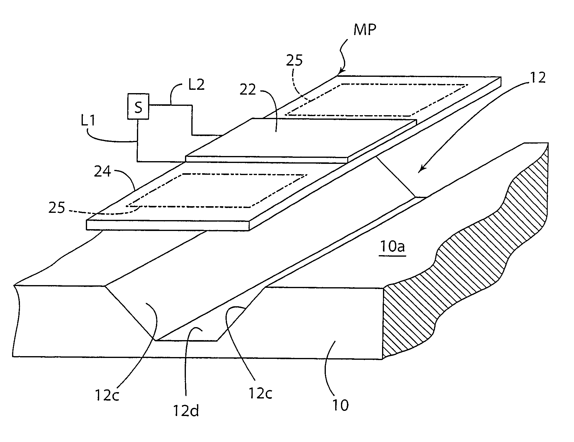
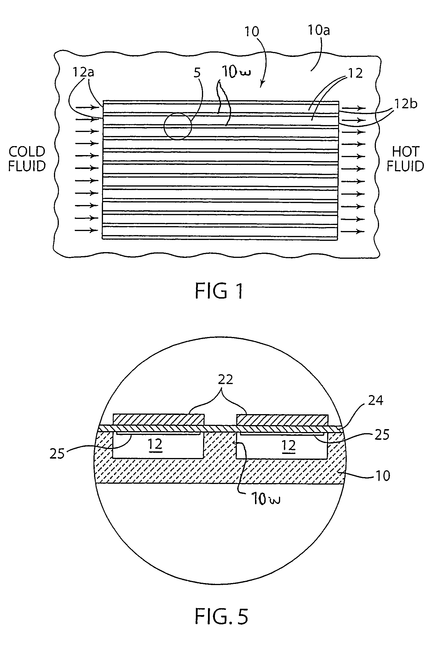
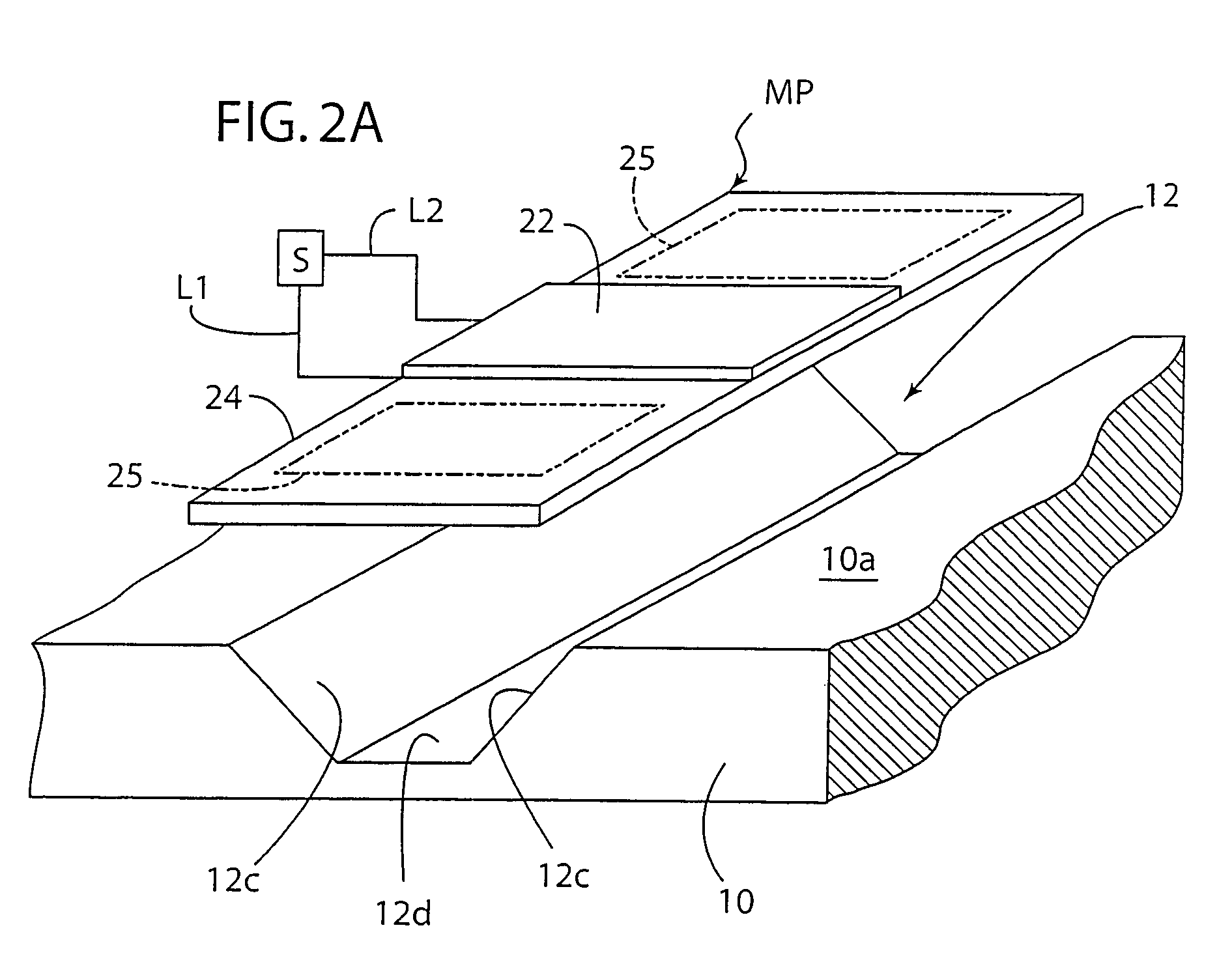
[0022]The present invention provides in an embodiment an electrohydrodynamic (EHD) micropump with fluid flow rate enhancement using a vibrating diaphragm, and useful for, although not limited to, removing heat from a heat-generating electronic component, such as for purposes of illustration and not limitation, a microelectronic IC chip (integrated circuit chip) of an electronic device such as cell phones, laptop computers, personal digital assistance devices, desktop computers, and the like as well as for delivering a drug, medicine or other treatment agent in or as a fluid to a patient. The micropump is advantageous in that it requires less space and electrical power as compared to a conventional micropumps and eliminates the need for an external pump for a microchannel heat sink, in that it provides increased and controllable volume flow rate of the working fluid, and in that it can be incorporated in a microchannel heat sink to provide an improved cooling system for heat-generati...


PUM


Abstract

A micropump including one or more microchannels for receiving a fluid and a plurality of electrodes arranged on a diaphragm and energized in a manner to provide an enhanced electrohydrodynamic flow of fluid through the one or more microchannels. The micropump may be used for pumping a working fluid for removing heat from a heat-generating electronic component or for delivery of a drug, medicine, or other treatment agent as or in a fluid to a patient.

Description

[0001]This application is a continuation of international PCT application PCT / US2004 / 040916 having international filing date of Dec. 8, 2004, which designates the United States, published in English under Article 21(2), which claims benefits and priority of U.S. provisional application Ser. No. 60 / 528,347 filed Dec. 10, 2003.FIELD OF THE INVENTION[0002]The invention relates to an electrohydrodynamic micropump with fluid flow rate enhancement.BACKGROUND OF THE INVENTION[0003]Rapidly decreasing features sizes and increasing power density in microelectronic devices has necessitated development of novel cooling strategies to achieve very high heat removal rates from these devices. For example, heat removal rates in excess of 200 W / cm2 have been projected for the next generation of personal computing devices. Microchannel heat sinks have the potential to achieve these heat removal rates and therefore have been studied for over two decades as described, for example, by Tuckerman and Pease...

Claims


Application Information

Patent Timeline
Patent Type & Authority Patents(United States)
IPC IPC(8): F04B37/02F04B17/00F04B43/04F04B53/10
CPCF04B43/043F04B43/046F04B53/1077
Inventor SINGHAL, VISHALGARIMELLA, SURESH V.
Owner PURDUE RES FOUND INC
Why Eureka
Try Eureka