Security element for marking or identifying objects and living beings

a security element and living being technology, applied in the field of security elements for marking, authenticating, or identifying objects, can solve the problems of inability to determine authenticity or only with great effort, the assignment of certain security elements remains an unresolved problem, and the forgery cannot be distinguished from the original, so as to improve forgery security, accelerate the formation of crackles, and improve the effect of forgery

Active Publication Date: 2014-08-21
KISTERS FRIEDRICH
View PDF16 Cites 4 Cited by
  • Summary
  • Abstract
  • Description
  • Claims
  • Application Information

AI Technical Summary

Benefits of technology

[0044]The crackle can vary in intensity depending on the layer thickness. For example, the crackle can be more intense in areas in which the layer is thicker, and less strong in areas in which the layer thickness is smaller. The layer thickness can thereby be used as a selective design tool to bring about the crackle. Depending on the type of employed solvent, this layer can dry either more rapidly or more slowly, which in turn means that the rate of crackle pattern formation can be influenced. This can be exploited if, for example, a document is to be valid only for a specific time period. If the crackle pattern in the database differs too greatly from the crackle pattern to be authenticated, then the document has expired, been manipulated, or forged. The pattern tolerance can be established by using a threshold value. Depending on the type of employed layer composition, the crackle effect can be more intense or less intense and thereby influence this time period. Depending on the physical or chemical method, the crackle can be set or undergo a dynamic aging process (a process of change or further development).
[0072]The crackle pattern with its tears, nicks, shrinkages, wear and / or soiled areas, and optionally other security features in the same or different areas of a layer can be scanned and acquired with different measuring methods or parameters, whereby each measuring method or each parameter can provide its own data set, which together or separately is acquired and optionally updated in one or more existing databases. A separate transmission and / or storage of the data hereby increase very greatly the protection of data access by unauthorized third parties. The establishment of these parameters and the selection of measuring methods can be flexible. It can occur randomly or according to a predefined logic or algorithm.

Problems solved by technology

However, because of the available possibilities for forgery, the absolutely certain assignment of such security elements has remained an unresolved problem thus far.
Further, an identical printed image with an identical protective lacquer can be applied to a forgery, as a result of which the forgery can no longer be distinguished from the original.
Determination of authenticity is not possible or possible only with great effort.
This system is not forgery-proof either.
In addition, the identity cannot be unequivocally assigned to a specific person.
False negatives and operator-, user-, or transmission-related errors also continue to be possible.
This production process, nevertheless, does not represent protection from copies, because all originals retain their specific security features and these can ultimately be reconstructed.
The aforementioned existing methods for authentication (access control) of persons or for marking of originals are inflexible, on the one hand, because they include predefined authentication steps.
On the other hand, they do not include any effective mechanism for protection against forgery.
In addition, existing systems are not capable of determining who an authorized person is, because they only compare information that they receive.
Apart from false-negative cases, false-positive cases are also a daily problem.
This type of three-factor authentication is not sufficient, however, because false negatives and other discrepancies can continue to occur.
Further, the consistency of the transmitted data is not checked, which enables possible hacker attacks.

Method used


Image

  • Security element for marking or identifying objects and living beings
  • Security element for marking or identifying objects and living beings
  • Security element for marking or identifying objects and living beings

Examples


Embodiment Construction

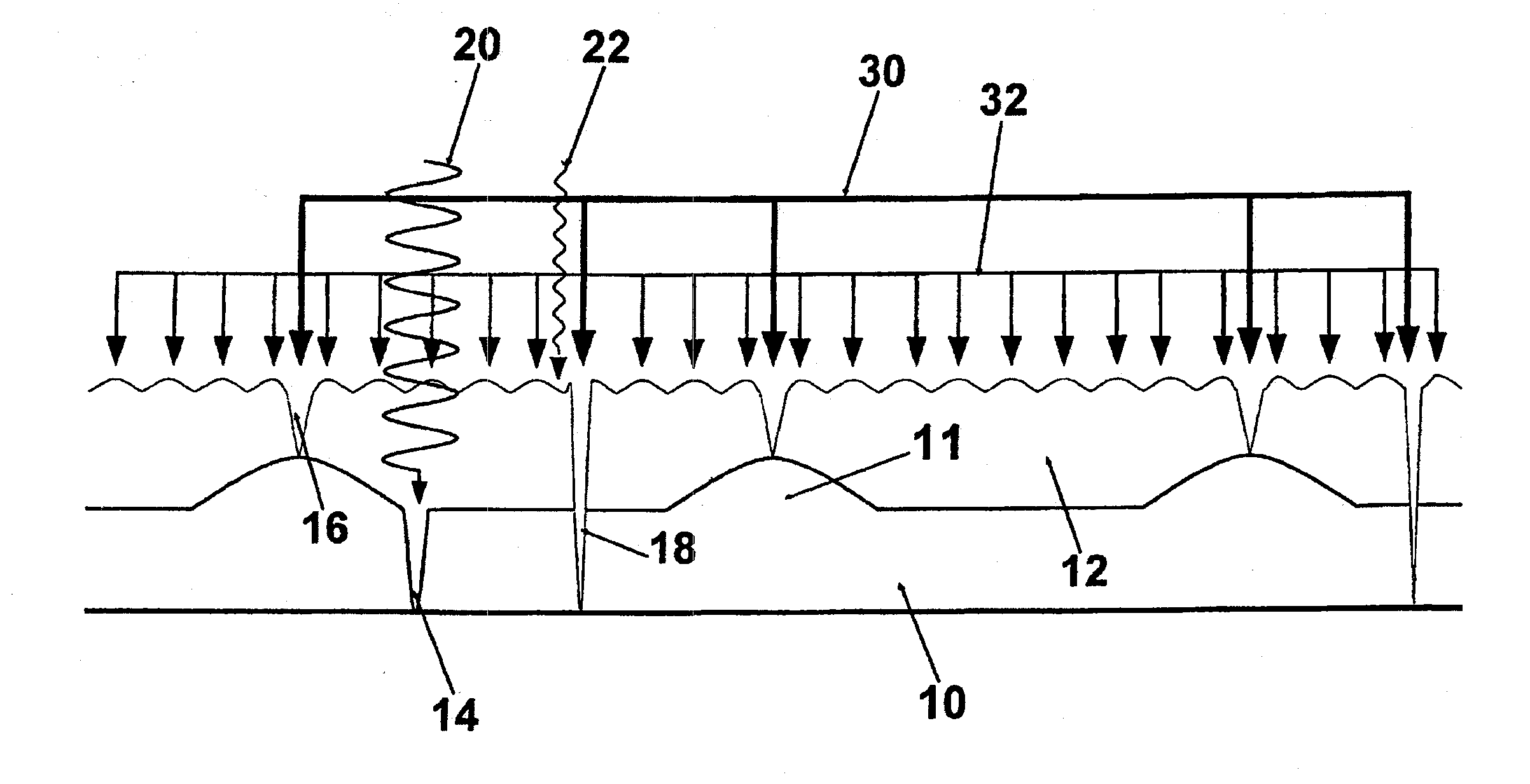
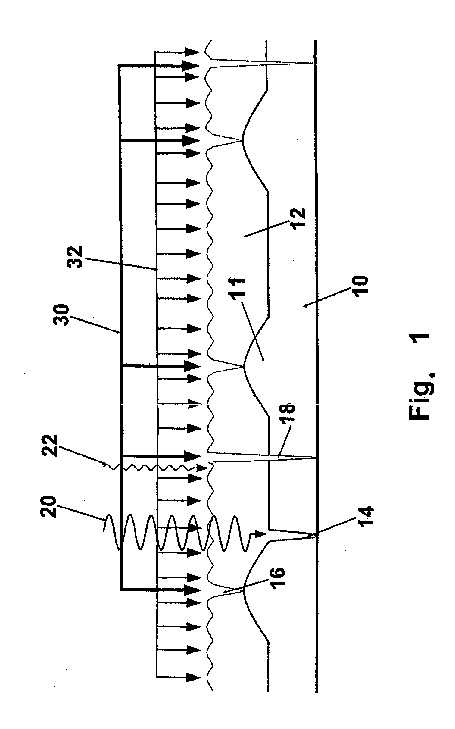
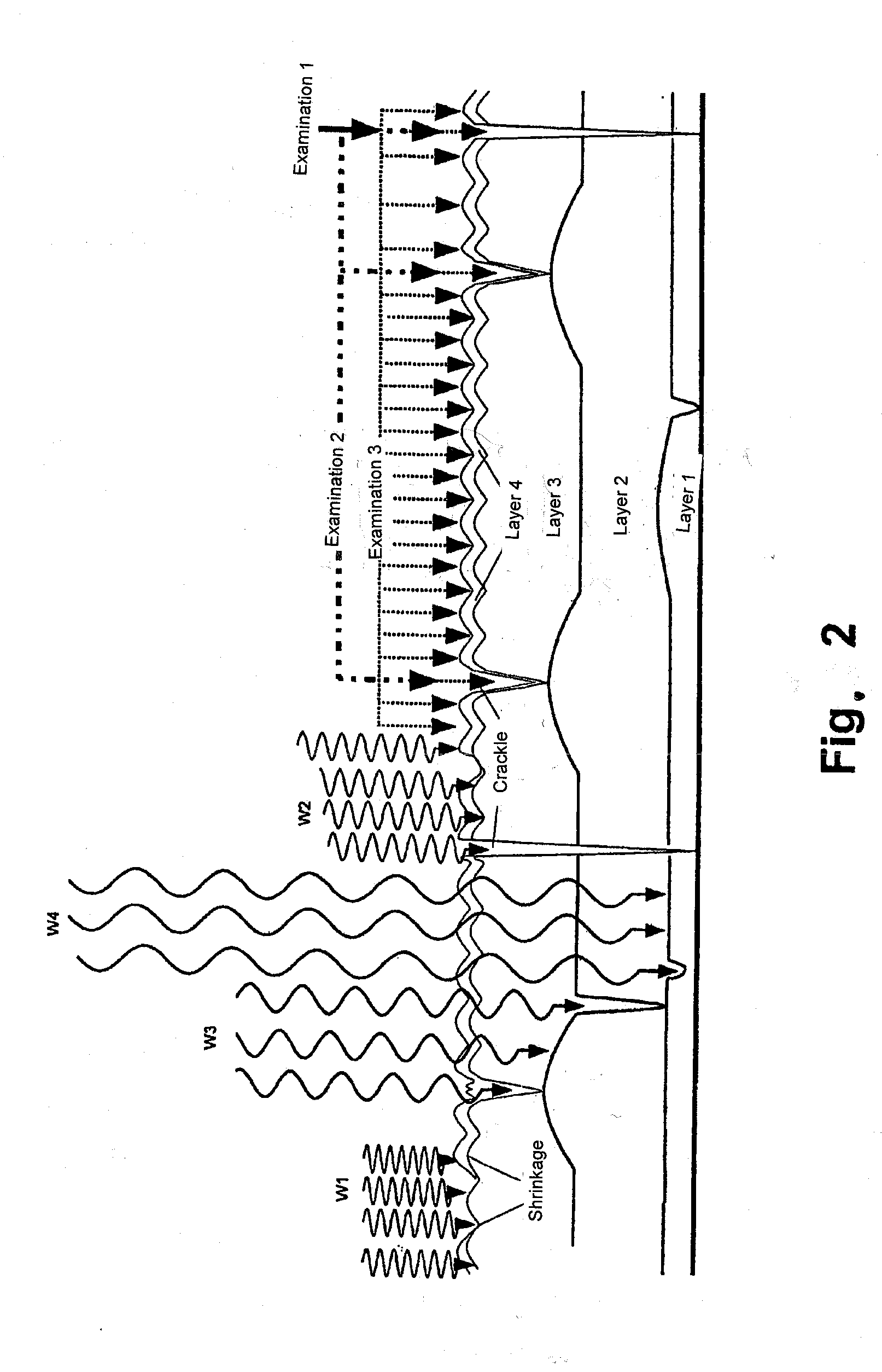
[0081]In FIG. 1, two crackle layers 10, 12 are arranged one above the other. The individual crackle layers 10, 12 form varyingly pronounced tears or cracks 14, 16, 18. Depending on the extent, the tears of the topmost layer 12 can pass through to the underlying layer 10 as a single tear (cf. tear 18). Tears 16 can arise in the topmost layer 12 because of the drying process. Such tears can arise, for example, also by the drying or shrinking 11 of the underlying layer 10. Naturally, also an overlying layer can influence an underlying layer and cause stress cracks. Depending on the employed method, tears can be introduced selectively in this way to create a crackle. If a layer shrinks, it can also form furrows, which are similarly characteristic like crackle structures. As a result, shrinkages can also be used as a security feature, apart from or in addition to the crackle structures.

[0082]The individual layers 10, 12 can be scanned by different measuring methods for data acquisition o...


PUM

PropertyMeasurementUnit
wavelengthaaaaaaaaaa
wavelengthsaaaaaaaaaa

Abstract

A security element for marking, authenticating or identifying objects or living beings, such as people, animals or plants is provided that includes one or more layers of materials that are arranged next to or on top of each other or that overlap, which have security markings. At least one layer of the security element has, at least regionally, a crackle pattern in form of tears or cracks, nicks, wear areas or shrinkages and possible impurities, which can be scanned and detected together or separately as security features. A method for producing such a security element and to a use thereof for authenticating a person or an object, or for authorizing, triggering, continuing, carrying out and ending an action is also provided.

Description

[0001]This nonprovisional application is a divisional of U.S. application Ser. No. 13 / 351,830, filed on Jan. 17, 2012, which is a continuation of International Application No. PCT / EP2010 / 004270, which was filed on Jul. 14, 2010, and which claims priority to German Patent Application No. DE 10 2009 033 221.9, which was filed in Germany on Jul. 14, 2009, and which are all herein incorporated by reference.BACKGROUND OF THE INVENTION[0002]1. Field of the Invention[0003]The present invention relates to a security element for marking, authenticating, or identifying objects, particularly documents, securities, stamps, labels, bank bills, bank notes, identity documents, personal identity cards, other ID cards, passports, (chip) cards, access cards, credit cards, access control cards, tickets, driver's licenses, vehicle documents, bank notes, checks, postage stamps, labels, vignettes, paintings, art objects, furniture, measuring devices, machine parts, machines, vehicles; cameras, cell phone...

Claims


Application Information

Patent Timeline
Patent Type & Authority Applications(United States)
IPC IPC(8): G07C11/00
CPCG07C11/00B42D25/21B42D25/29B42D25/405B42D2035/34Y10T29/49
Inventor KISTERS, FRIEDRICH
Owner KISTERS FRIEDRICH
Why Eureka
Try Eureka