Scrap submergence system

a submergence system and scrap technology, applied in the direction of manufacturing converters, lighting and heating apparatus, furnaces, etc., can solve the problems of affecting the speed of submergence in molten metal, high oxidation loss, and difficult melting of thin walled scrap pieces, etc., to achieve the effect of improving compatibility

Active Publication Date: 2014-08-21
PYROTECK INC
View PDF0 Cites 71 Cited by
  • Summary
  • Abstract
  • Description
  • Claims
  • Application Information

AI Technical Summary

Benefits of technology

[0008]The present disclosure further provides an apparatus and method having improved compatibility with the variety of molten metal furnace configurations that exist.

Problems solved by technology

Melting thin walled scrap pieces is particularly difficult because (i) extended exposure to the hostile atmosphere in a traditional melting furnace results in extremely high oxidation loss and, (ii) rapid submergence in molten metal is severely hampered by the fact that thin walled scrap pieces float on molten metal.

Method used


Image

  • Scrap submergence system
  • Scrap submergence system
  • Scrap submergence system

Examples


Embodiment Construction

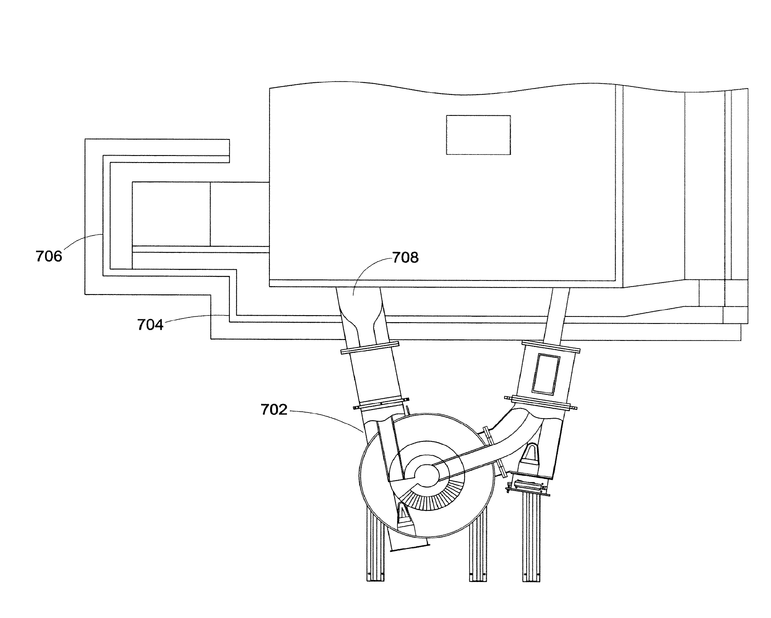
[0036]According to a first aspect of the invention, processing apparatus for molten metal is provided. The apparatus includes a furnace chamber for the molten metal, a pump, an outlet leading from the furnace chamber to the pump, an outlet leading from the pump to a charge well and a passage leading from the charge well to the furnace chamber. The processing apparatus may be for melting metal or metal containing materials and / or for processing molten metal and / or for purifying molten metal and / or for distributing molten metal. The pump can be a centrifugal or electromagnetic.

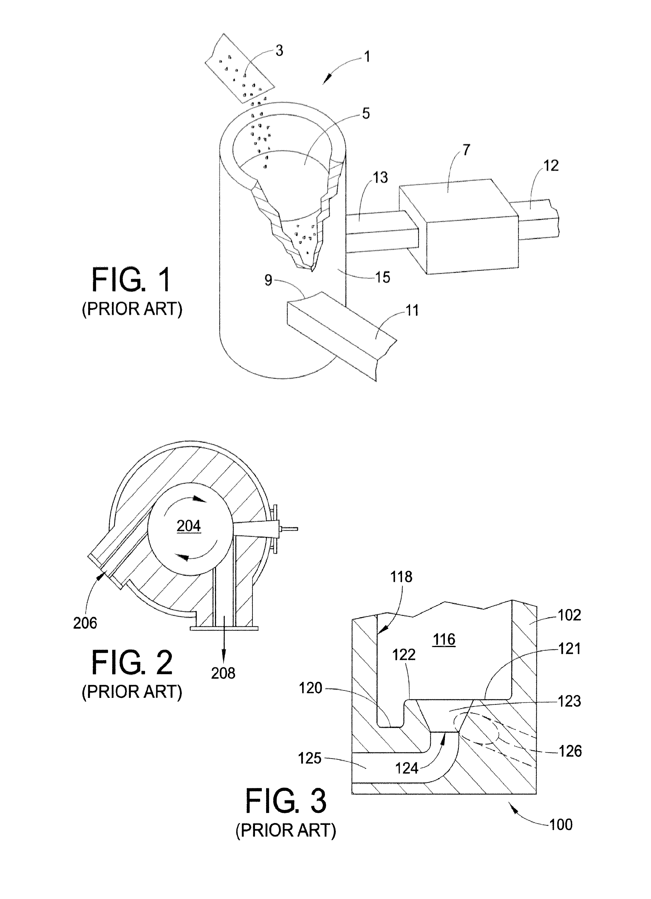
[0037]With reference to FIG. 3, in a cold start or in a dry furnace condition, the vortexing well of the device described in U.S. Pat. No. 6,217,823 has proven problematic if used as the charge well of the system depicted in FIG. 1. Moreover, if the molten metal processing system is at a low metal level (dry hearth), inner wall 122 serves as a dam to the flow of molten metal and an impediment to molten metal flo...


PUM

PropertyMeasurementUnit
angleaaaaaaaaaa
angleaaaaaaaaaa
angleaaaaaaaaaa

Abstract

In accordance with one aspect of an exemplary embodiment, a furnace including a charge well is provided. The charge well comprises an open top chamber including side and base walls of a heat resistant material. An inlet is provided in a side wall of the chamber for receiving molten metal. A ramp is provided adjacent the side wall and an inner wall forms a central cavity. The ramp is disposed between the inner wall and the side wall. The ramp is generally inclined from an intersection with the base wall to adjacent a top surface of the inner wall. The cavity is in fluid communication with an outlet. A passage in the inner wall provides fluid communication between the inlet and the cavity. The inlet and an outlet each receives a conduit and at least one of the conduits can include an elbow joint.

Description

[0001]This application claims the benefit of U.S. Provisional Application No. 61 / 505,156, filed Jul. 7, 2011 and U.S. Provisional Application No. 61 / 625,134, filed Apr. 17, 2012, the disclosures of each are herein incorporated by reference.BACKGROUND[0002]The present invention is directed to a scrap submergence system of the type typically employed in molten metal processing. For example, it has application in the recycling of aluminum, but is not limited thereto. In the recycling of metals, it is necessary to melt scrap pieces for treatment and processing. A large portion of the scrap pieces are thin walled as a result of the mechanical shaping action from which they are formed, such as, shaving, boring and cold rolling. Melting thin walled scrap pieces is particularly difficult because (i) extended exposure to the hostile atmosphere in a traditional melting furnace results in extremely high oxidation loss and, (ii) rapid submergence in molten metal is severely hampered by the fact...

Claims


Application Information

Patent Timeline
Patent Type & Authority Applications(United States)
IPC IPC(8): F27B3/04F27B3/18
CPCF27B3/18F27B3/045C22B7/003C22B21/0092F27D27/00Y02P10/20F27B3/04
Inventor HOWITT, ROGERGRAYSON, JIMBOLTON, MARKBOSWORTH, PAUL
Owner PYROTECK INC
Why Eureka
Try Eureka