Power transmission system

a transmission system and power technology, applied in underwater equipment, special-purpose vessels, instruments, etc., can solve the problems of increasing both the time required and the cost, and the inability to collect data relating to water quality or travel through water, so as to prevent the magnetic field from being disrupted, and achieve high efficiency and long distance

Active Publication Date: 2014-08-21
IHI CORP
View PDF2 Cites 49 Cited by
  • Summary
  • Abstract
  • Description
  • Claims
  • Application Information

AI Technical Summary

Benefits of technology

[0014]In the present invention, a magnetic field resonance system is employed for underwater power transmissions between a power-transmitting device and a power-receiving device. Compared to an electromagnetic induction system, this magnetic field resonance system is largely unaffected by positional shifting of the resonance coils that are provided in both the power-transmitting device and the power-receiving device (i.e., is tolerant of positional shift), and is able to perform power transmissions highly efficiently and over long distances using only a weak magnetic field.
[0015]Accordingly, according to the present invention, a high-accuracy positioning mechanism such as is used in the conventional technology which employs an electromagnetic induction system is rendered unnecessary. As a consequence, it is possible to achieve underwater power transmissions at low cost between a power-transmitting device and a power-receiving device. Moreover, in the present invention, at least one of the resonance coils of the power-transmitting device and the power-receiving device is covered by a balloon. As a result, it is possible to prevent the magnetic field being disrupted by the effects of ions and the like contained in the water, and to thereby prevent the power transmission efficiency between the power-transmitting device and the power-receiving device from deteriorating.

Problems solved by technology

Naturally, if the residual battery power of the autonomous underwater vehicle drops to zero, it becomes impossible to collect data relating to the water quality or to travel through the water.
In this manner, if the autonomous underwater vehicle is recovered to the surface vessel each time the battery needs charging, then both the time required and the costs increase enormously.

Method used


Image

  • Power transmission system
  • Power transmission system
  • Power transmission system

Examples


Embodiment Construction

[0021]Hereinafter, an embodiment of the present invention will be described with reference made to the drawings.

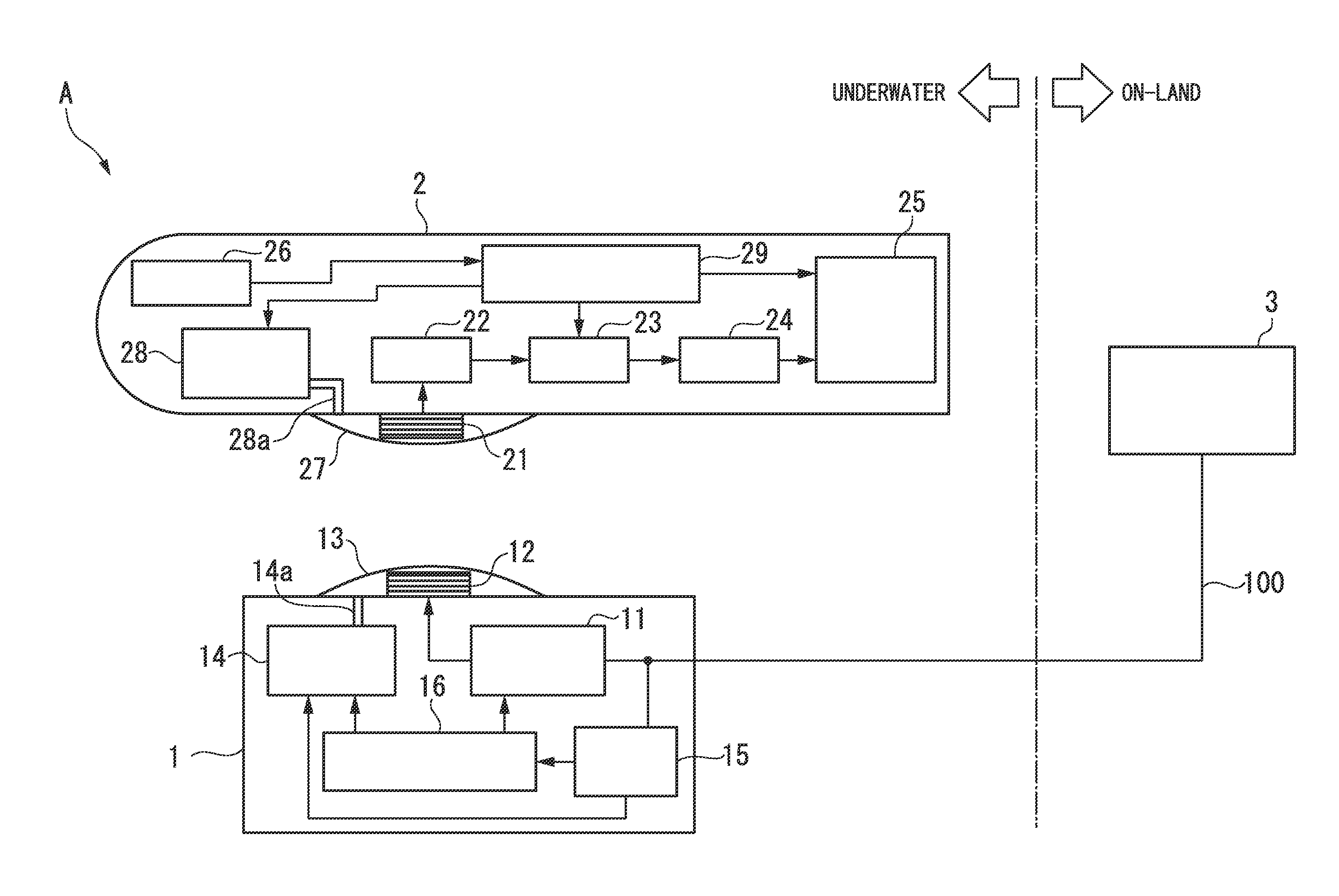
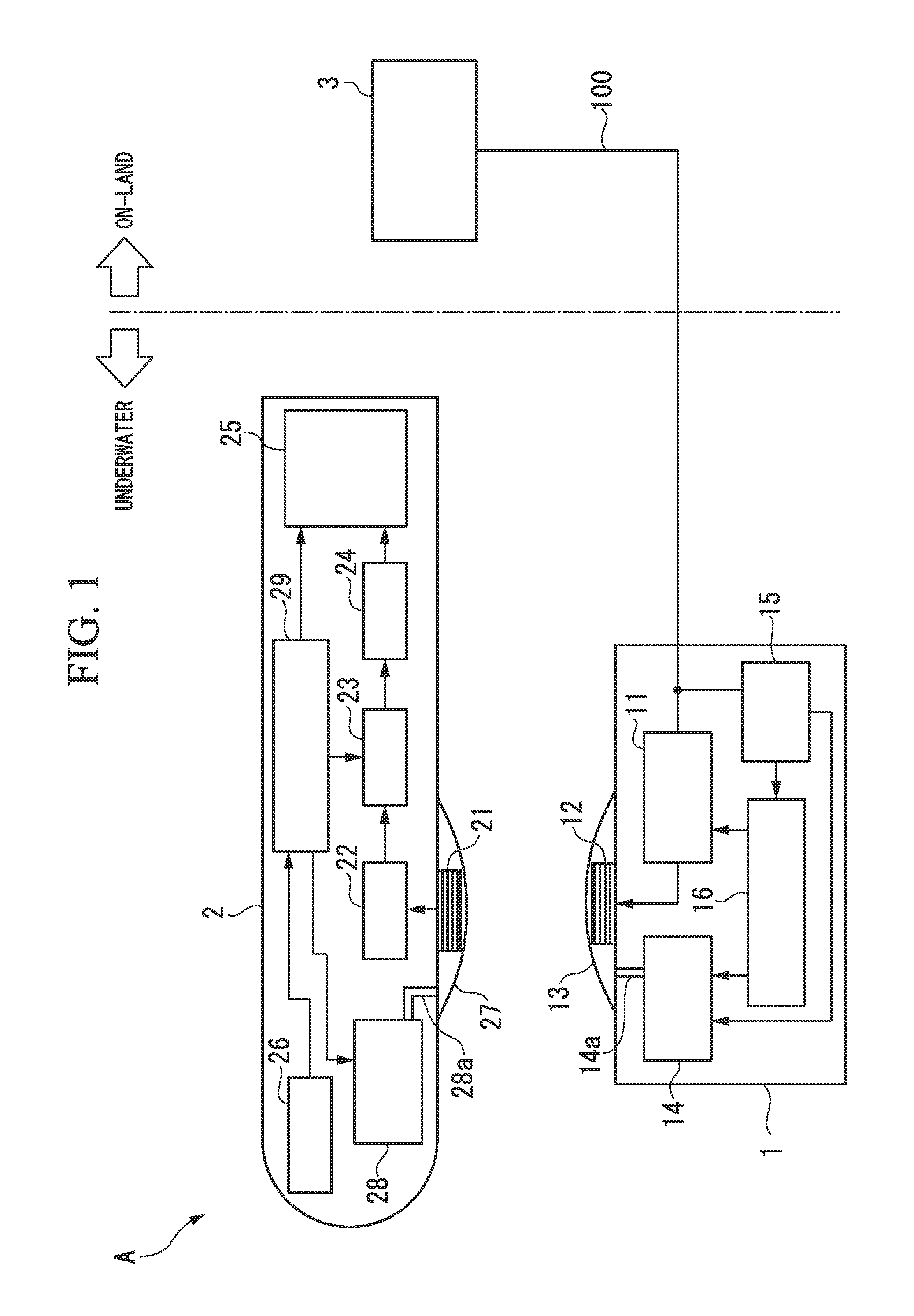
[0022]FIG. 1 is a schematic structural view of a power transmission system A according to the present embodiment. As is shown in FIG. 1, the power transmission system A is provided with an underwater base station 1 (i.e., a power-transmitting device) that is installed in a predetermined underwater location, and an autonomous underwater vehicle 2 (i.e., a power-receiving device) that is able to move freely underwater by means of battery power, and with an electrical power system 3 that is installed on land.

[0023]The underwater base station 1 is connected via a power supply cable 100 to the on-land electrical power system 3, and wirelessly transmits (i.e., supplies) AC power (for example, 100 V single-phase power having a frequency of 50 or 60 Hz) that is supplied from the electrical power system 3 to the autonomous underwater vehicle 2 by means of magnetic field resonance. ...


PUM


Abstract

A power transmission system transmits power underwater between a power-transmitting device and a power-receiving device of which at least one is capable of moving freely underwater. In this power transmission system, the power-transmitting device and the power-receiving device are each provided with a resonance coil that performs the power transmission wirelessly underwater by means of magnetic field resonance. At least one of the power-transmitting device and the power-receiving device is provided with a balloon that internally houses the resonance coil of its own device.

Description

[0001]This application is a continuation application based on a PCT Patent Application No. PCT / JP2012 / 081781, filed Dec. 7, 2012, whose priority is claimed on Japanese Patent Application No. 2011-268250, filed Dec. 7, 2011. The contents of both the PCT application and the Japanese Patent Application are incorporated herein by reference.TECHNICAL FIELD[0002]The present invention relates to a power transmission system.BACKGROUND ART[0003]Conventionally, a method of examining the water quality of sea water using an autonomous underwater vehicle that travels through water by means of battery power is known. Naturally, if the residual battery power of the autonomous underwater vehicle drops to zero, it becomes impossible to collect data relating to the water quality or to travel through the water. Because of this, when the residual battery power drops below a specified value, it is normal for the autonomous underwater vehicle to be recovered to a surface vessel so that the battery can be...

Claims


Application Information

Patent Timeline
Patent Type & Authority Applications(United States)
IPC IPC(8): H02J7/02H02J7/00B63C11/00
CPCH02J7/025H02J5/005B63G8/001B63G8/08G01N33/1886B63B2211/02B63G2008/008H02J2310/42H02J7/0042H02J50/005H02J50/402H02J50/90H02J50/12
Inventor MAEKAWA, YUJI
Owner IHI CORP
Why Eureka
Try Eureka