

Solenoid-driven automatic transfer switch
- Summary
- Abstract
- Description
- Claims
- Application Information
AI Technical Summary
Benefits of technology
Problems solved by technology
Method used
Image

Examples
Embodiment Construction
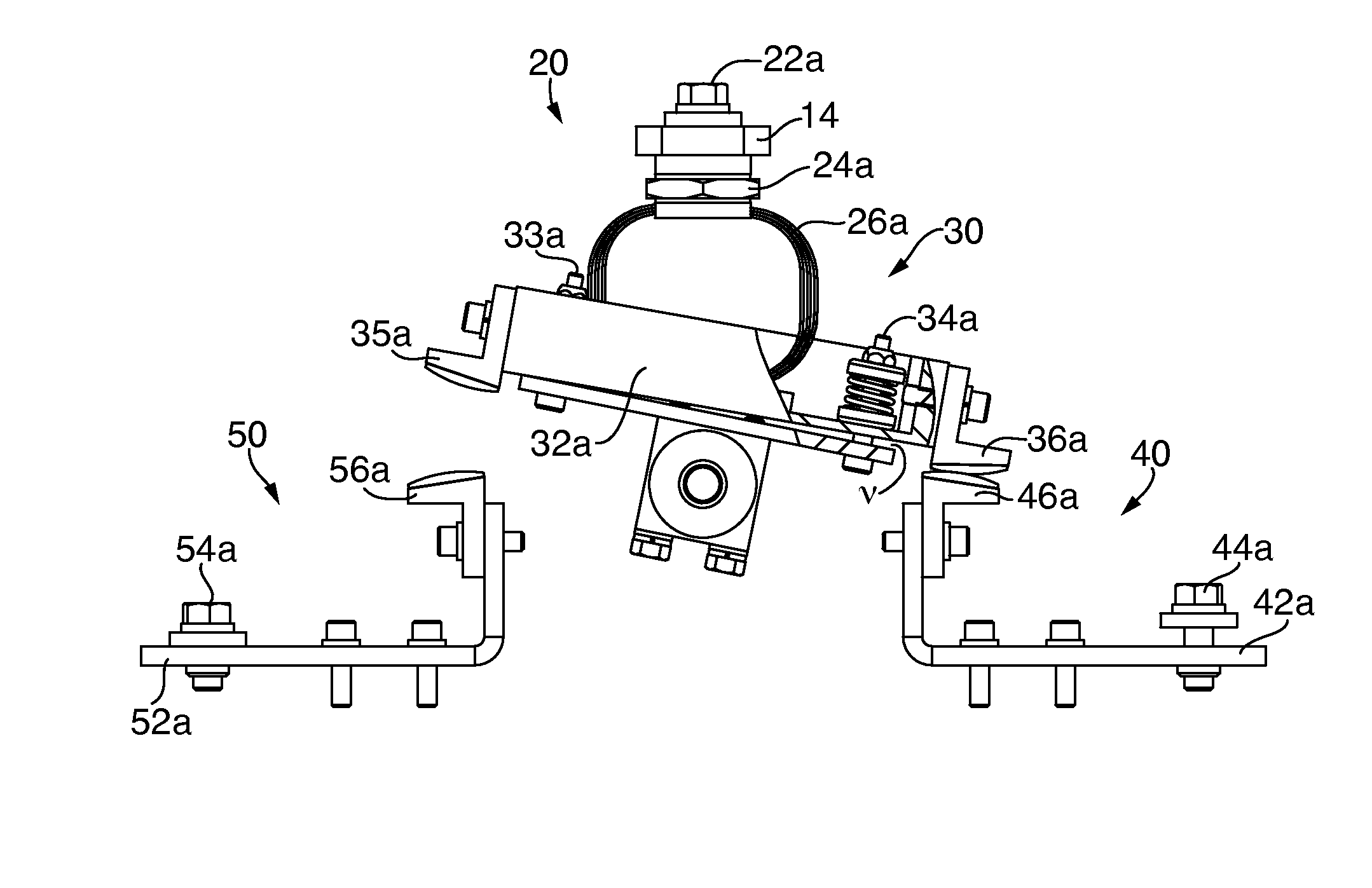
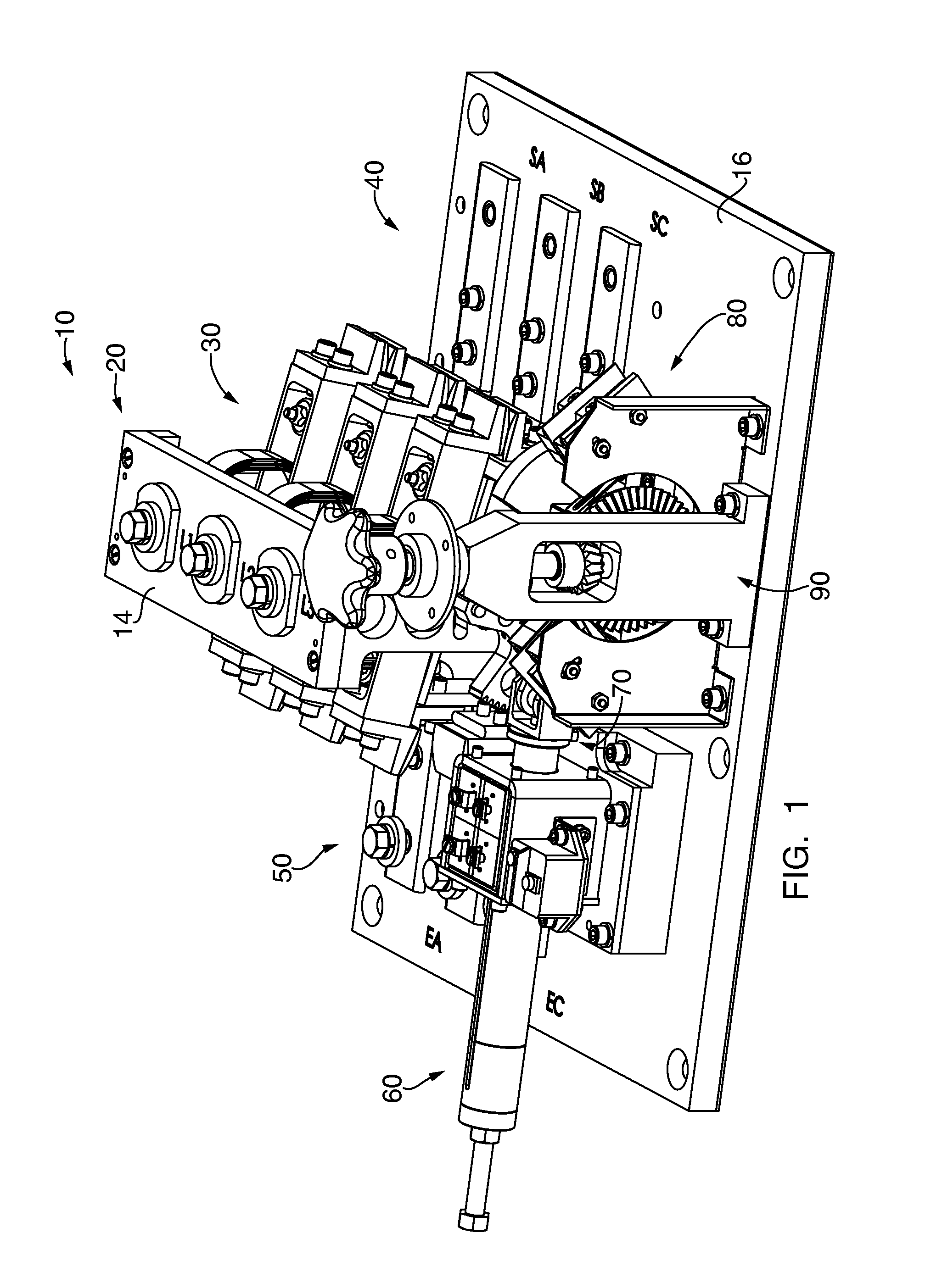
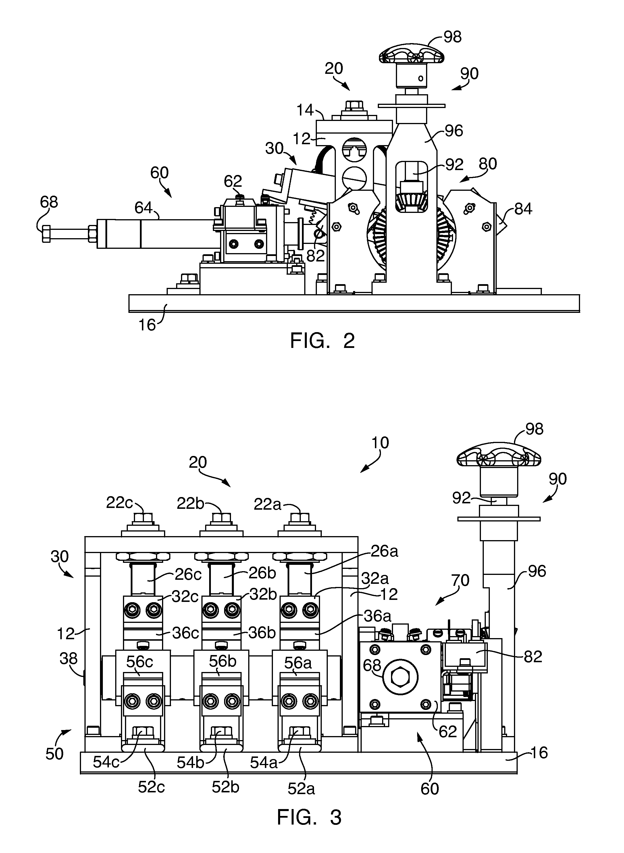
[0030]Referring to FIGS. 1-6, an automatic transfer switch 10 according to embodiments of the present disclosure is shown. The embodiment of the transfer switch 10 depicted in FIGS. 1-6 is generally intended to provide three-phase alternating current (AC) power from either a normal (or primary) power source or an alternate (or secondary) power source to a three-phase AC load. However, those of ordinary skill in the art would recognize that the systems and methods disclosed therein are not limited to providing AC power to loads, or to application in three-phase AC power environments, and may be utilized to provide AC power in any number of phases (e.g., single-phase) as well as direct current (DC) power to one or more loads.
[0031]As is depicted in FIGS. 1-6, the transfer switch 10 comprises a load assembly 20 for providing electrical power to one or more loads, and a transfer assembly 30 for switching the source of the power provided to the load assembly 20 from a normal side (or pri...
PUM
 Abstract
Description
Claims
Application Information