Device and method for imaging an ocular fundus

a technology of ocular fundus and imaging device, which is applied in the field of devices and methods for imaging an ocular fundus, can solve the problems of limiting resolution, affecting the detection accuracy of such devices and methods, so as to reduce the number of optoelectronic sensors and prevent the extension of the data acquisition period.

Active Publication Date: 2014-08-21
CARL ZEISS SMT GMBH
View PDF4 Cites 33 Cited by
  • Summary
  • Abstract
  • Description
  • Claims
  • Application Information

AI Technical Summary

Benefits of technology

[0026]The at least one further TDI camera can be set up to record the stray light image simultaneously to the recording of the image of the ocular fundus with the optoelectronic sensor. Due to the temporally parallel recording with the primary optoelectronic sensor and the at least one further TDI camera, an extension of the data acquisition period can be prevented.
[0027]The arrangement for recording the stray light image can comprise at least one further radiation source, which is arranged offset to the ra

Problems solved by technology

However, the numerical aperture for detection in such devices and methods can frequently be very small which limits the resolution.
Furthermore, with this operating principle, fundus images can frequently be fraught with a high stray light background since wide-field detection is applied.
This can lead to a relatively poor signal-to-background ratio in bright-field images or fluorescence images.
However, with many eyes, it is difficult to illuminate with blue and green light through the sclera since the absorp

Method used


Image

  • Device and method for imaging an ocular fundus
  • Device and method for imaging an ocular fundus
  • Device and method for imaging an ocular fundus

Examples


Embodiment Construction

[0048]In the following, embodiments of the invention are described in detail. The features of different embodiments can be combined with one another unless specified otherwise. The description of an embodiment which combines a number of features must not be interpreted such that all such features are required for the execution of the invention since other embodiments can have fewer features and / or alternative features.

[0049]In the drawings, similar or identical elements are denoted with similar or identical reference signs.

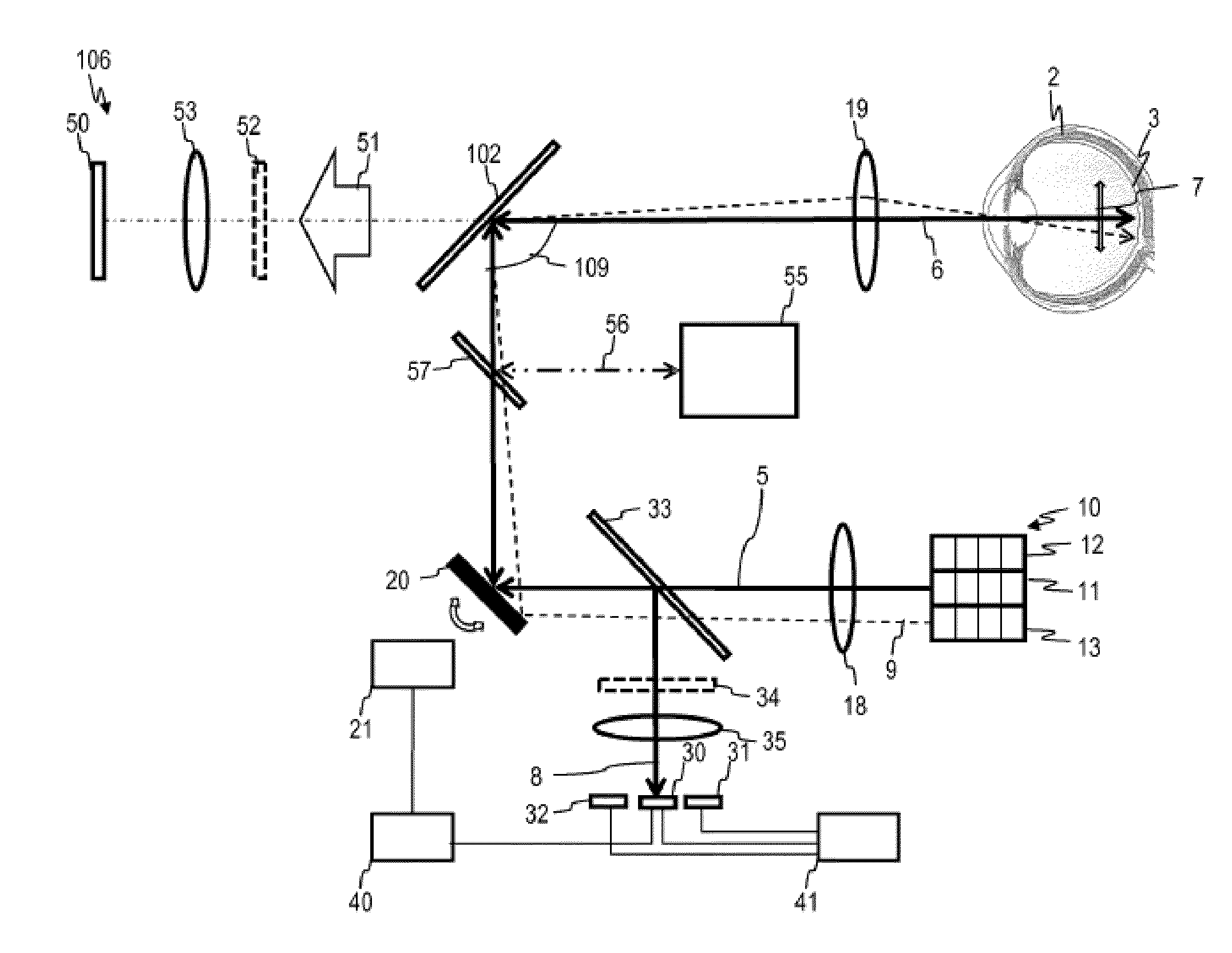
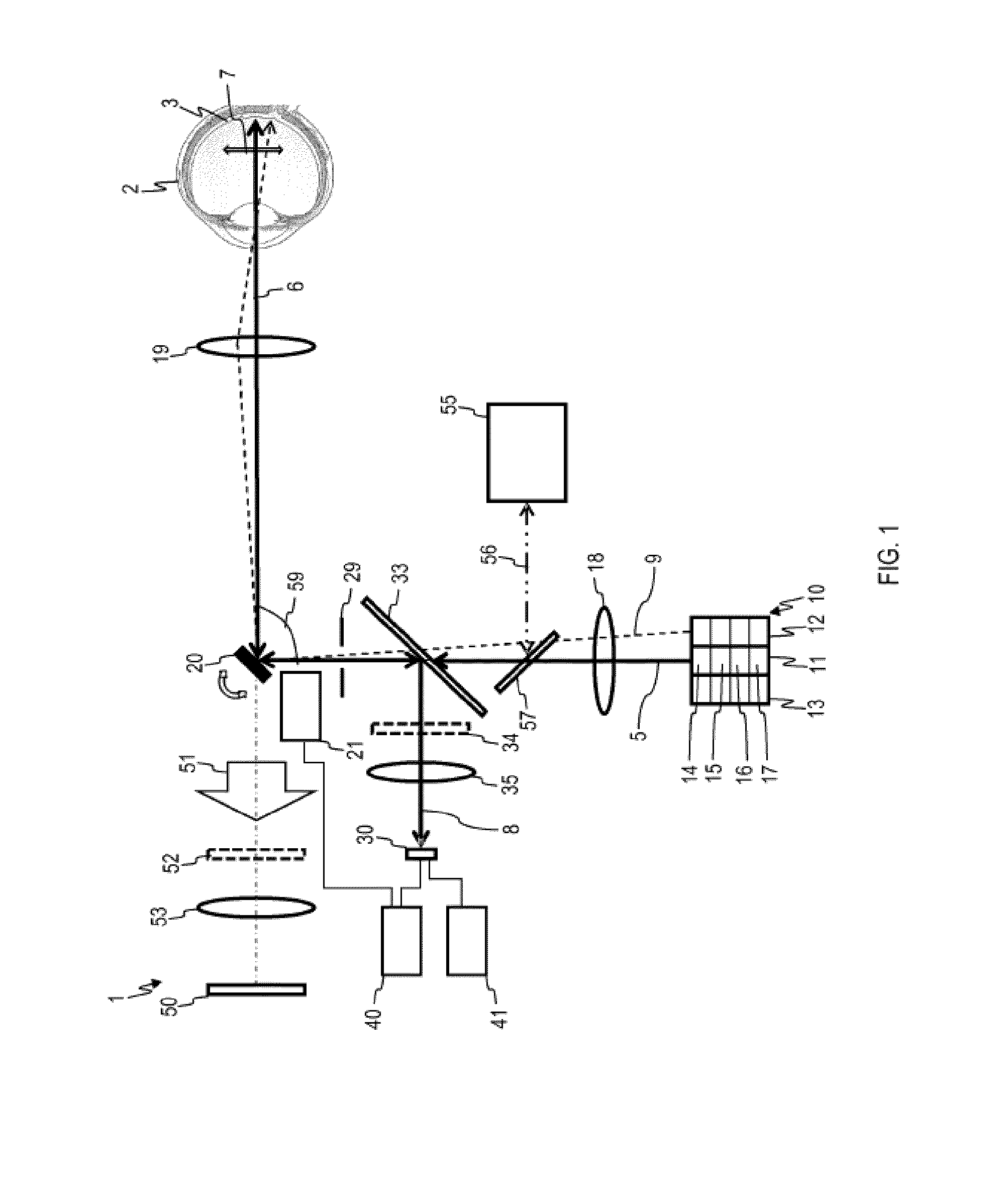
[0050]The embodiments described in the following relate to devices and methods for imaging an ocular fundus, for example, for funduscopy (ophthalmoscopy). An eye, particularly a human eye, is illuminated and the detection light originating from the ocular fundus is recorded. The device can be designed particularly such that the inside of the eye or the ocular fundus is illuminated through the pupil. Devices according to embodiments can be designed, for example, as...


PUM


Abstract

An appliance for recording an image of an ocular fundus includes an irradiating device with a radiation source and optical components for generating an illumination strip. A scanning device is set up to cause a scanning movement of the illumination strip for the purpose of scanning the ocular fundus. An optoelectronic sensor senses detection light issuing from the ocular fundus. The optoelectronic sensor has a plurality of sensor rows and is set up such that charges contained in one sensor row are each shifted, with a time delay, into a further sensor row. A control means is connected to the scanning device and/or to the optoelectronic sensor and is set up to control the scanning movement and/or the time delay.

Description

RELATED APPLICATIONS[0001]The present application is a National Phase entry of PCT Application No. PCT / EP2012 / 068605, filed Sep. 21, 2012, which claims priority to DE Application No. 10 2011 053 880.1 filed Sep. 23, 2011, which applications are hereby incorporated by reference herein in their entirety.FIELD OF THE INVENTION[0002]The invention relates to devices and methods for imaging an ocular fundus. The invention particularly relates to devices and methods for imaging an ocular fundus which use an optoelectronic sensor for recording a digital image of the ocular fundus.[0003]Devices and methods for imaging an ocular fundus are used for examining the eye, particularly the human eye. In the following, the ocular fundus (“fundus oculi”) will also be called fundus. Devices and methods for imaging the ocular fundus are used, for example, for the diagnosis of diseases of a retina of an eye, particularly a human eye. For example, the use of so-called fundus cameras in combination with f...

Claims


Application Information

Patent Timeline
IPC IPC(8): A61B3/12A61B3/14A61B3/00
CPCA61B3/12A61B3/14A61B3/0008A61B3/158
Inventor WESTPHAL, PETERBUBLITZ, DANIEL
Owner CARL ZEISS SMT GMBH
Why Eureka
Try Eureka