Method and apparatus for auto-correcting the distributed temperature sensing system

a distributed temperature sensing and automatic correction technology, applied in the field of temperature sensing, can solve the problems of long time, high cost, and inability to accurately correct the temperature measurement in the distributed system, and achieve the effect of reliable and accurate temperature calculation

Inactive Publication Date: 2014-08-21
LEE CHUNG
View PDF14 Cites 15 Cited by
  • Summary
  • Abstract
  • Description
  • Claims
  • Application Information

AI Technical Summary

Benefits of technology

[0012]This new disclosure can provide a reliable and accurate temperature calculation by 1) auto correcting the DAF issue and 2) wide temperature range application without the temperature effect subtraction from the Stokes band because this scheme utilizes the ratio of temperature sensitive Anti-Stokes and temperature insensitive Rayleigh signals, both are located in same spectral bands and 3) continuously compensating the fluctuations in the light source output intensities.

Problems solved by technology

The resultant distributed measurement is equivalent to the performances of thousands of ‘point temperature’ sensors, which usually are susceptible to electric noises, occasional fire incidents due to wire shorted circuits and complicated installation—costly and take long periods of time.
The first issue is the inherent characteristics of anti-Stokes band, which are not only sensitive to temperature variation but also to physical perturbations, which induce the attenuation of the light transmitting along the fiber.
The second issue is the DAF (Differential Attenuation Factor) due to the material characteristics of optical fiber.
But in many real application cases, various perturbations are applied or generated unintentionally to the section of sensing fiber cable times after deployment.
These environmental effects are called the ‘darkening’ in a local section or sections of the fiber and induce different attenuation values to each 1, resulting in erroneous temperature profile.
The issue of this method is the requirement of two channels, which requires twice the measurement time, double the length of sensing fiber and twice the optical budget.
Also DE configuration is not permissible for some critical applications.
The challenging job is the process of continuous in-situ correction for DAF and the subtraction of the temperature dependency of S band in high temperature application.
But interpolation is an indirect correction method, and there may be a practical implementation limit to match and keep the wavelengths stable.

Method used


Image

  • Method and apparatus for auto-correcting the distributed temperature sensing system
  • Method and apparatus for auto-correcting the distributed temperature sensing system
  • Method and apparatus for auto-correcting the distributed temperature sensing system

Examples


Embodiment Construction

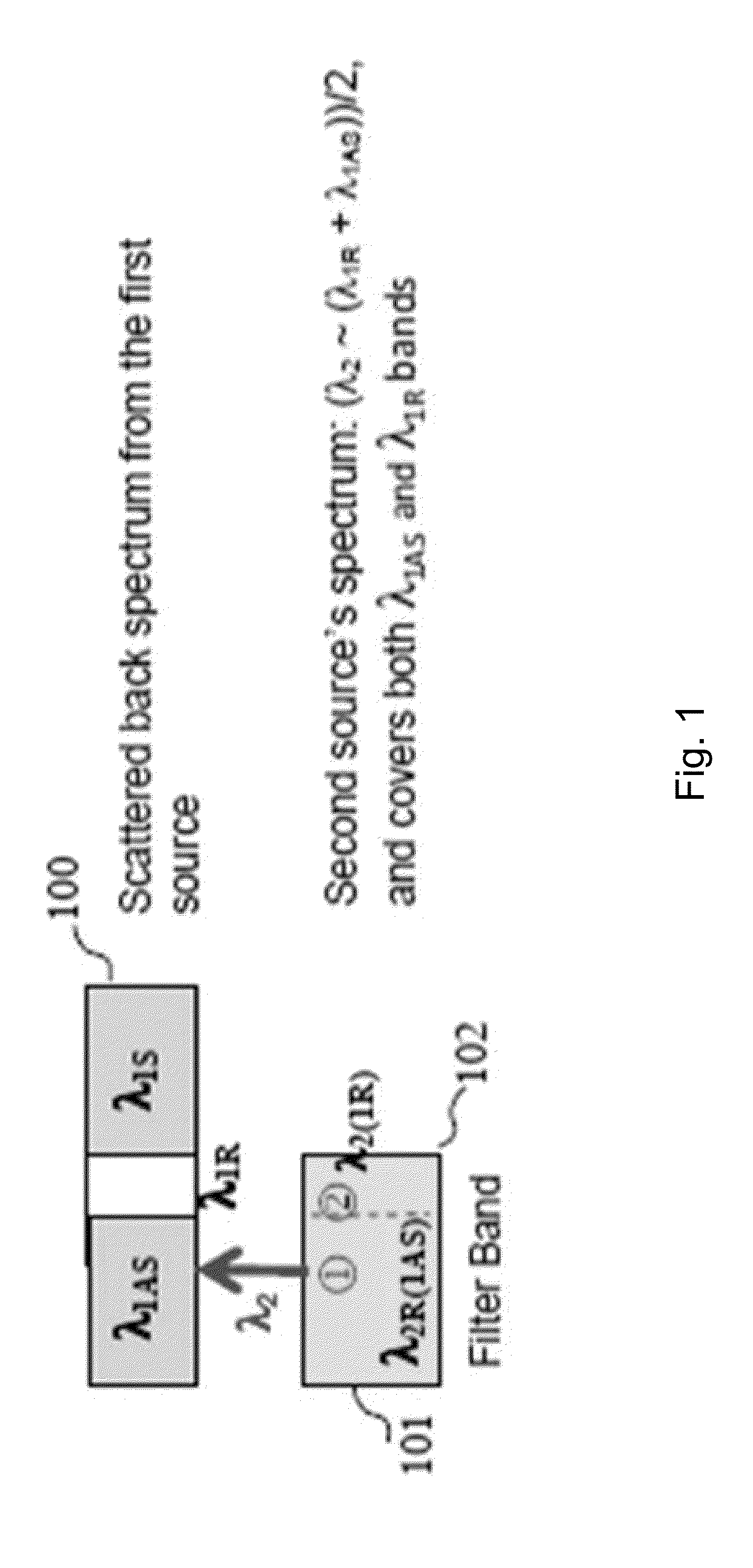
[0024]FIG. 1 shows the spectral requirements to select the secondary light source. The top figure illustrates 3 spectral bands 100 of the first (or primary) light source, anti-Stokes, Rayleigh and Stokes respectively. The bottom figure shows the secondary source's spectral components. The center wavelength of the secondary is selected to be located in the middle of anti-Stokes 101 and Rayleigh bands 102 of the primary source and are wide enough to cover both spectral bands. A three port (one input and two outputs) wavelength selector is used to select two bands, λ1AS, λ1R, or λ2R,1AS and λ2R,1R or λ2,1R.

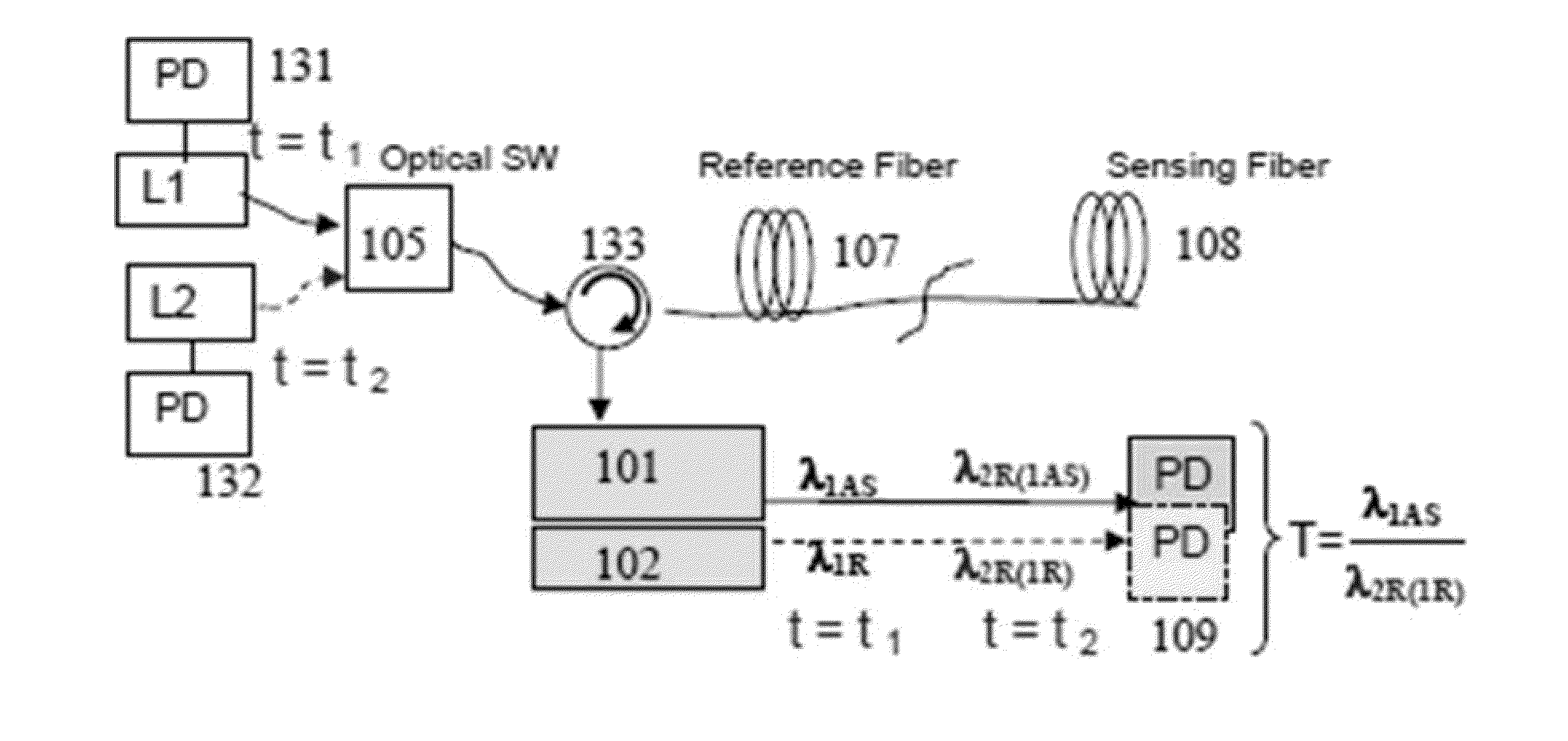
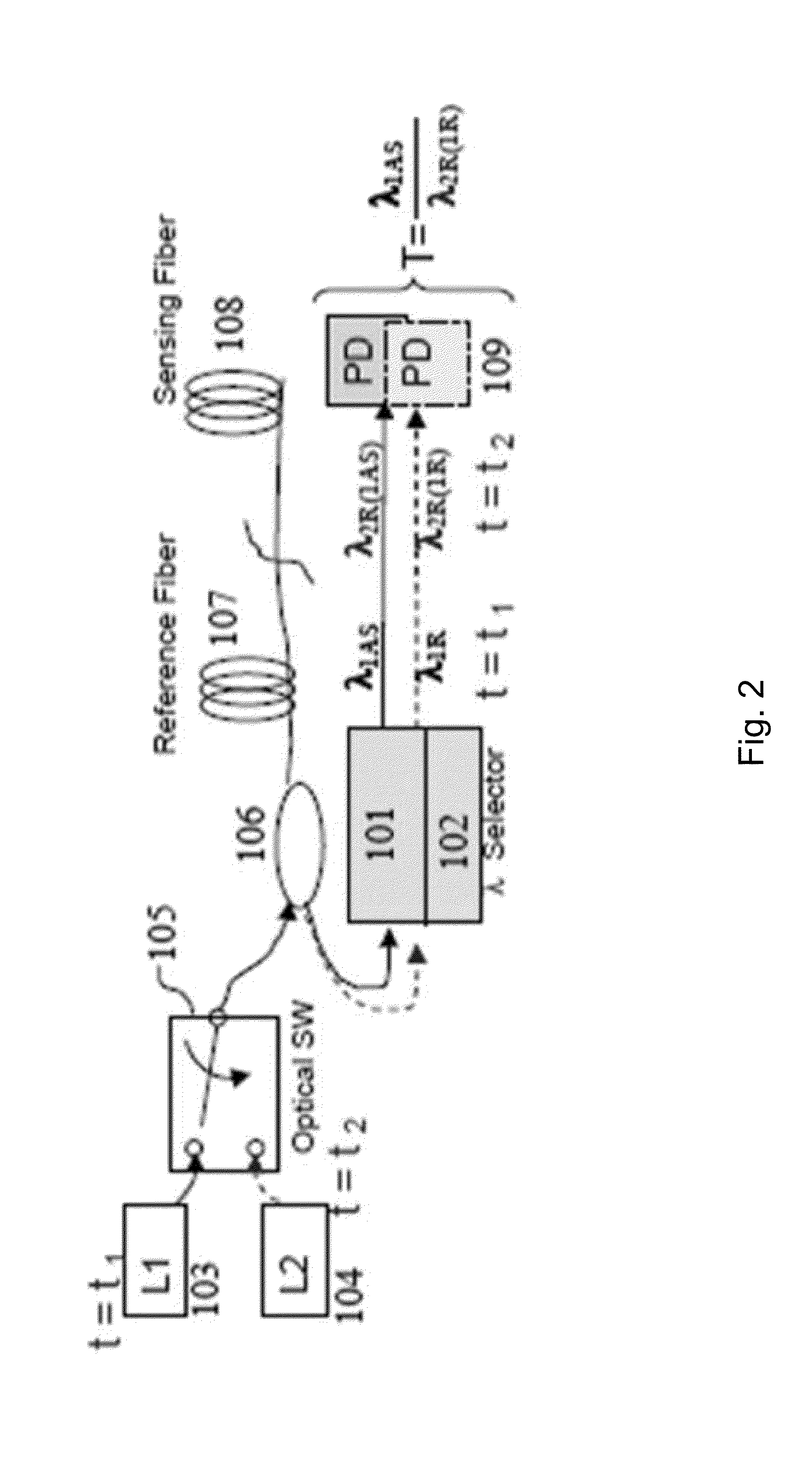
[0025]FIG. 2 shows the embodiment of the system diagram. Two light sources, the primary source 103, L1 (conventional laser type) and the secondary 104, L2 (a SLD light source) chosen as the conditions mentioned in the previous page is consecutively selected by an optical switch, 105 to select L1 first (at time=t1) and inject the light to the sensing fiber through the coupler, 106. It...


PUM

PropertyMeasurementUnit
temperatureaaaaaaaaaa
center wavelengthaaaaaaaaaa
electric switchingaaaaaaaaaa

Abstract

System and method for correcting the potential errors occurring in a fiber optic temperature measurement system are disclosed. In one respect, a dual light sources configuration is provided. The primary light source may illuminate a sensing fiber, and an Anti-Stokes band may be detected. The secondary light source may illuminate a sensing fiber, and a Rayleigh band may be detected, where the Rayleigh band is substantially wide enough to cover the Anti-Stokes band of the primary light source. A ratio between these Anti-Stokes and the Rayleigh bands may be used to measure the temperature and undesired errors due to the perturbations falling on the sensing fiber is continuously corrected.

Description

CROSS-REFERENCE TO RELATED APPLICATIONS[0001]This applications claims priority to U.S. Provisional Patent Application Ser. No. 61 / 766,639, filed Feb. 19, 2013, which is hereby incorporated by reference in its entirety.FIELD OF THE INVENTION[0002]The present invention relates generally to temperature sensing. More particularly, the present disclosure relates to system for automatically correcting the temperature measurement in a distributed system.BACKGROUND OF THE INVENTION[0003]Optical fibers have been used mainly for optical communication systems for decades. Recently, optical fiber sensing technologies have grown rapidly due to their advantages over conventional sensing devices. The optical fiber sensors can handle much higher signal bandwidth and temperature ranges, are immune to electromagnetic interference noises, provide safe operation (no generation of electric sparks which occasionally induce catastrophic fire incidents), and require a much easier installation process. But ...

Claims


Application Information

Patent Timeline
Patent Type & Authority Applications(United States)
IPC IPC(8): G01K15/00
CPCG01K15/005G01K11/32
Inventor LEE, CHUNG
Owner LEE CHUNG
Why Eureka
Try Eureka