Method for auto-depicting trends in object contours

a technology of object contours and trend detection, applied in image analysis, instruments, computing, etc., can solve the problems of deviation or error, incomplete object contours cannot be created, and subsequent image processing is likely to be worse than expected, so as to improve method reliability, accurately depict edge curvature, and select an angular value

Inactive Publication Date: 2014-08-21
ICP ELECTRONICS +1
View PDF1 Cites 4 Cited by
  • Summary
  • Abstract
  • Description
  • Claims
  • Application Information

AI Technical Summary

Benefits of technology

[0022]The present invention has three key technical ideas. One key technical idea is to take advantage of a second region for staying a step ahead of detecting the trend of the contour in a first region and retrieving the angular values within the second region, and take the second significant angular value as the reference angular value, wherein the second significant angular value is obtained by performing angular value screening upon the edge angular values extracted from the second region. Next, the reference angular value is regarded as the basis for updating the first significant angular value. The overall concept of the co-operation between the two regions is like the military march, wherein the second region (probe region) is like a scout in the army and is responsible for staying a step ahead of collecting information and returning to the rear of the army for the commander to determine whether to correct the moving direction of the military. A benefit of utilizing a probe region to detect and return the information in advance is to improve the reliability of the method for depicting trends in object contours of the present invention. If the second region were not employed for retrieving the angular values in advance to update the first significant angular value, the edge angular values contained in the first region would not be able to accurately depict the curvature of the edge in the case that an edge is curved seriously. At this situation, there is an error between the first significant angular value (which is selected through the angular value screening) and the actual trend of the edge; if the error is not corrected immediately, it will be accumulated and become larger and larger, leading to an inaccurate depicted contour. Like the aforementioned example of the military march, if there were no scout for detecting in advance, the enemy's whereabouts would not be known instantly. To put it another way, it is hard to make adjustments for tactics to deal with the movement of the enemy, and it is also hard to know the accurate position as well. The proposed method of the present invention utilizes angular values rather than edge intensity values adopted in the prior art design (e.g., Japanese Patent Publication No. 2001-319239). If the information for determining the edge / contour trends is based on the edge intensity values, the edge / contour trends may depart from the main edge direction due to coordinate contained in a messy edge point with a larger edge intensity value. Even if the messy edges are distributed within the region, the present invention still can perform angular value screening upon a plurality of edge angular values inside the region for finding out the main edge / contour trend (as indicated by the asterisk in FIG. 7). In other words, the proposed method of the present invention is able to find out the edge / contour trends consistent with the human perception.
[0023]Another key technical idea of the present invention is to set two angular value screening ranges, where the second angular value screening range is larger than the first angular value screening range. The main function of the angular value screening range is to filter out a portion of the noise interference and the angular values of the edges which are not the main edges, wherein the main edges are representative of the edges which are desired to be depicted. The reason why the second angular value screening range is set to be larger than the first angular value screening range is based on the consideration that the second angular value screening range is utilized for detecting and retrieving the reference angular values of the likely orientation. Excessively narrowing the angular value screening range will miss a lot of edge angular values, thus losing information of the likely orientation. On the other hand, the reason of setting the first angular value screening range by a smaller value is that since the reference angular values of the likely orientation are obtained, narrowing down the range may help to select an angular value from it fast and accurately. In other words, taking the aforementioned army march for example, if we have knew the enemy is located approximately at six to eight o'clock positions, then the military should adjust its march direction mainly towards six to eight o'clock positions according to the information in conjunction with the actual situation, rather than marching blindly (a larger angular value screening range).

Problems solved by technology

However, in a case where many image processing processes do not use the results obtained by depicting trends in object contours, but only use edge detection results as the input of the subsequent image processing, the results of the subsequent image processing is likely to be worse than expected.
As a result, the complete object contour can not be created.
For example, when the background of the input image is complex, there is noise interference, and / or there is changing light and shadow, this could easily lead to the case of deviation or error of the depicted trends in object edge / contour.
In other words, the conventional method which selects the closest edge is not robust enough, and is prone to be affected by the small difference of the input image (e.g., the light source) to therefore make the depicting result not properly fit the trends in object contours and even take the edges which belong to different contours to be the same trend in the object contour.
When the background of the input image is more complex (e.g., the background includes woods, bushes, etc.) or the noise interference is severe, the coordinate position of the next target pixel is prone to be wrong.

Method used


Image

  • Method for auto-depicting trends in object contours
  • Method for auto-depicting trends in object contours
  • Method for auto-depicting trends in object contours

Examples


embodiment 1

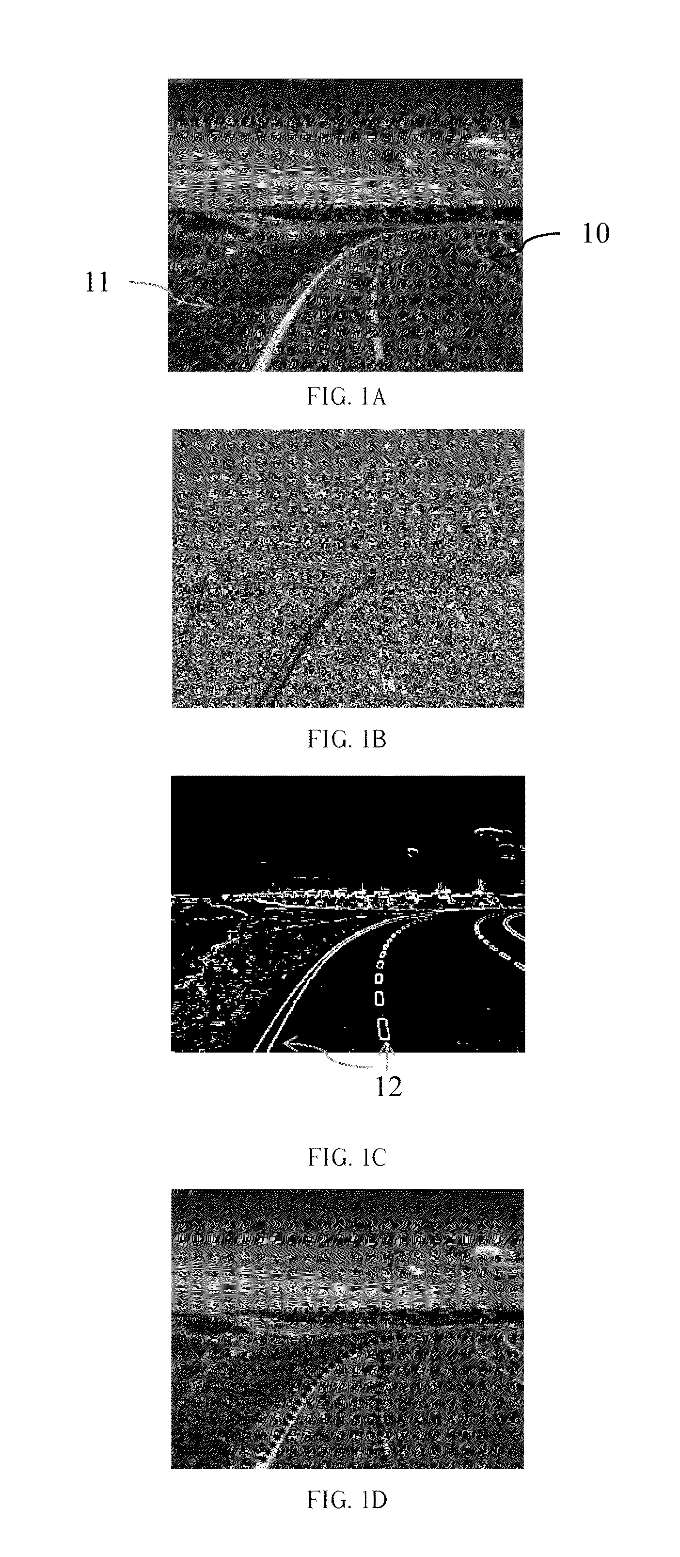
[0047]FIG. 1A is an input image containing a roadway. First, if the input image is a color image, the color image will be converted to a grayscale image. The conversion of the color image to grayscale is performed by using software such as Adobe Photo Shop, Ulead Photo Impact, etc. FIG. 1B and FIG. 1C are an angular value distribution diagram (angular values are indicated by different grayscale values) and an edge detection result (white points indicate the edges) respectively obtained from FIG. 1A through the step S2. The step S2 is to retrieve and extract coordinates and angular values of the image edges by an edge detection method, where the edge detection method may be referred to as a method capable of obtaining gradient information. For example, the edge detection method may employ a conventional edge detection algorithm such as Sobel, Prewitt, Roberts, etc.

[0048]Sobel algorithm is taken as an example of the edge detection method, and the equations for calculating a plurality ...

embodiment 2

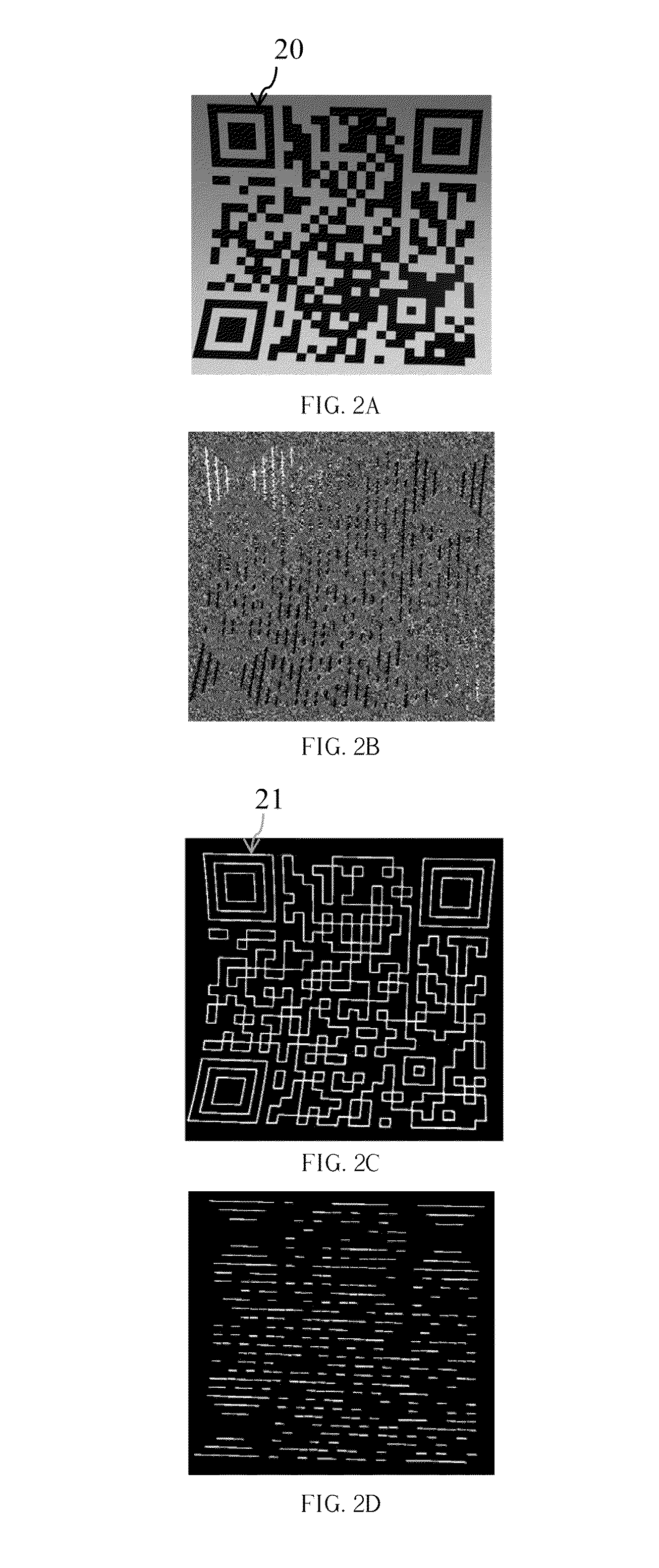
[0073]FIG. 2A is an input image containing a QR code. First, if the input image is a color image, the color image will be converted to a grayscale image. The conversion of the color image to grayscale is performed by using software such as Photo Shop, Photo Impact, etc. FIG. 2B and FIG. 2C are an angular value distribution diagram (angular values are indicated by different grayscale values) and an edge detection result (white points indicate the edges) respectively obtained from FIG. 2A through the step S2. The step S2 is to retrieve and extract coordinates and angular values of the image edges by utilizing an edge detection method, where the edge detection method may be referred to as a method capable of obtaining gradient information. For example, the edge detection method may employ a conventional edge detection algorithm such as Sobel, Prewitt, Roberts, etc.

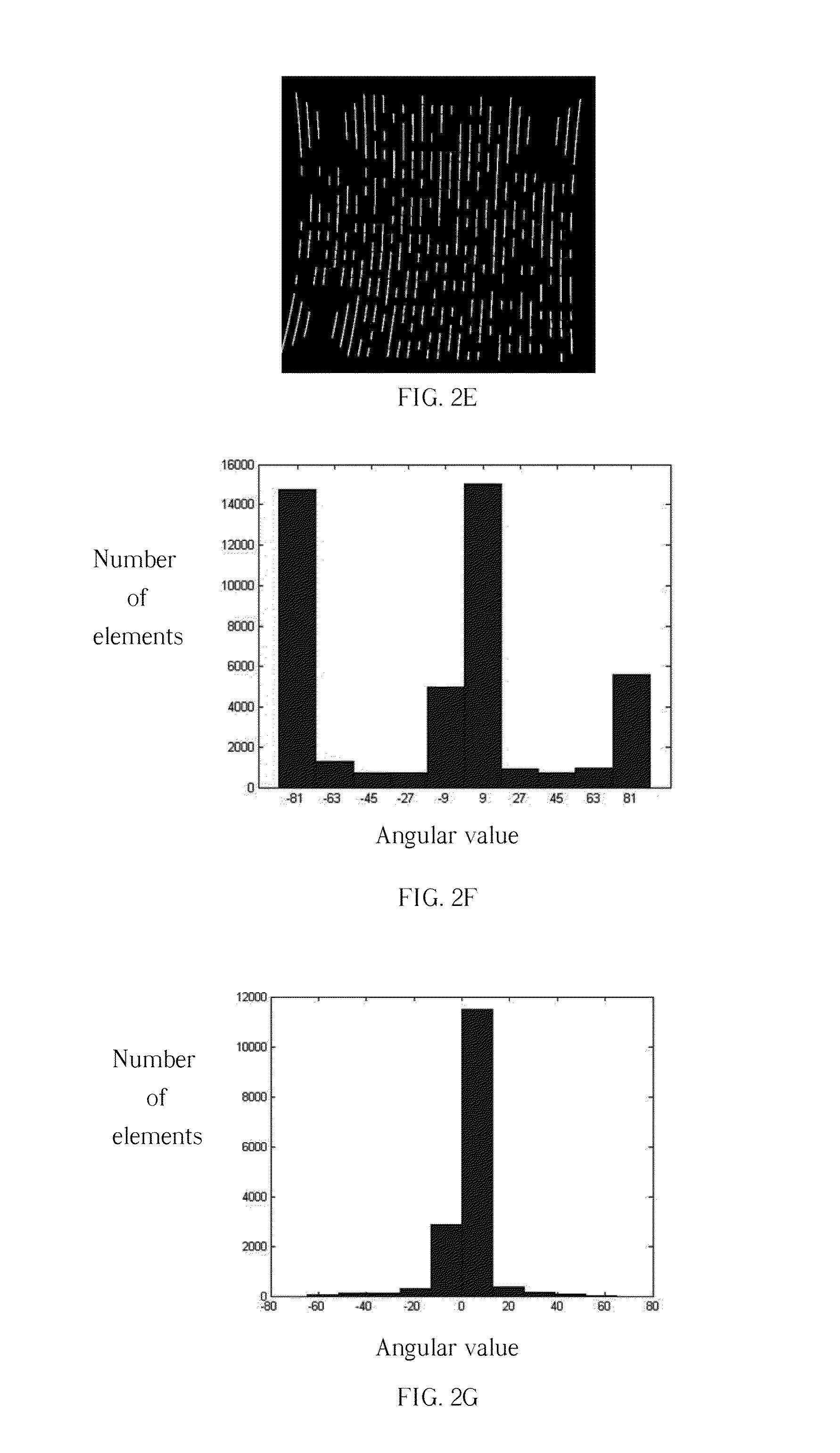
[0074]Sobel algorithm is taken as an example of the edge detection method, and a plurality of angular values θ and a plural...


PUM


Abstract

Disclosed herein is a method for auto-depicting trends in object contours (referred to as ADTOC). At the heart of ADTOC is a sifting process to determine a significant angular value via evaluating a plurality of angular values in a predefined range. ADTOC is characterized in that a probe-ahead concept is applied to obtain a reference angular value along the current route, and then the probed angular value is used to modify the significant angular value in order to timely correct the subsequent trace direction, thus achieving more accurate trace result. Contours with discontinuous segments caused by noise, obstacles, illumination, shading variations, etc. can also be auto-depicted without requiring a predefined auxiliary route.

Description

BACKGROUND OF THE INVENTION[0001]1. Field of the Invention[0002]The present invention relates to a method of image processing technology, and more particularly, to a method for auto-depicting (tracking) trends in object contours.[0003]2. Description of the Prior Art[0004]The method for depicting trends in object contours is considered to be a very important image processing technique. The reason is due to that more complete is the object contours depicted, more accurate the characteristics of the object, such as size, shape, or number, are recorded. These records may make the subsequent image processing be performed more easily and faster. The subsequent image processing refers to technologies that utilize the results of the edge detection for extended treatment such as scene analysis and pattern recognition. Regarding the technologies in practical applications, if we want to use less hardware resource or computing power to achieve better image processing performance, the edge detec...

Claims


Application Information

Patent Timeline
Patent Type & Authority Applications(United States)
IPC IPC(8): G06T7/00
CPCG06T7/0085G06T7/2033G06T7/13G06T7/246
Inventor TSENG, CHUN-SHUNWANG, JUNG-HUATSAI, SHAN-CHUNLIN, CHIAO-WEILIN, CHANG-TEWANG, YI-HUA
Owner ICP ELECTRONICS
Why Eureka
Try Eureka