Ferrule fixing member
a fixing member and ferrule technology, applied in the field of ferrule fixing members, can solve the problems of increasing assembly man-hours and components costs, and achieve the effect of reducing manufacturing costs and simple structur
- Summary
- Abstract
- Description
- Claims
- Application Information
AI Technical Summary
Benefits of technology
Problems solved by technology
Method used
Image

Examples
embodiment
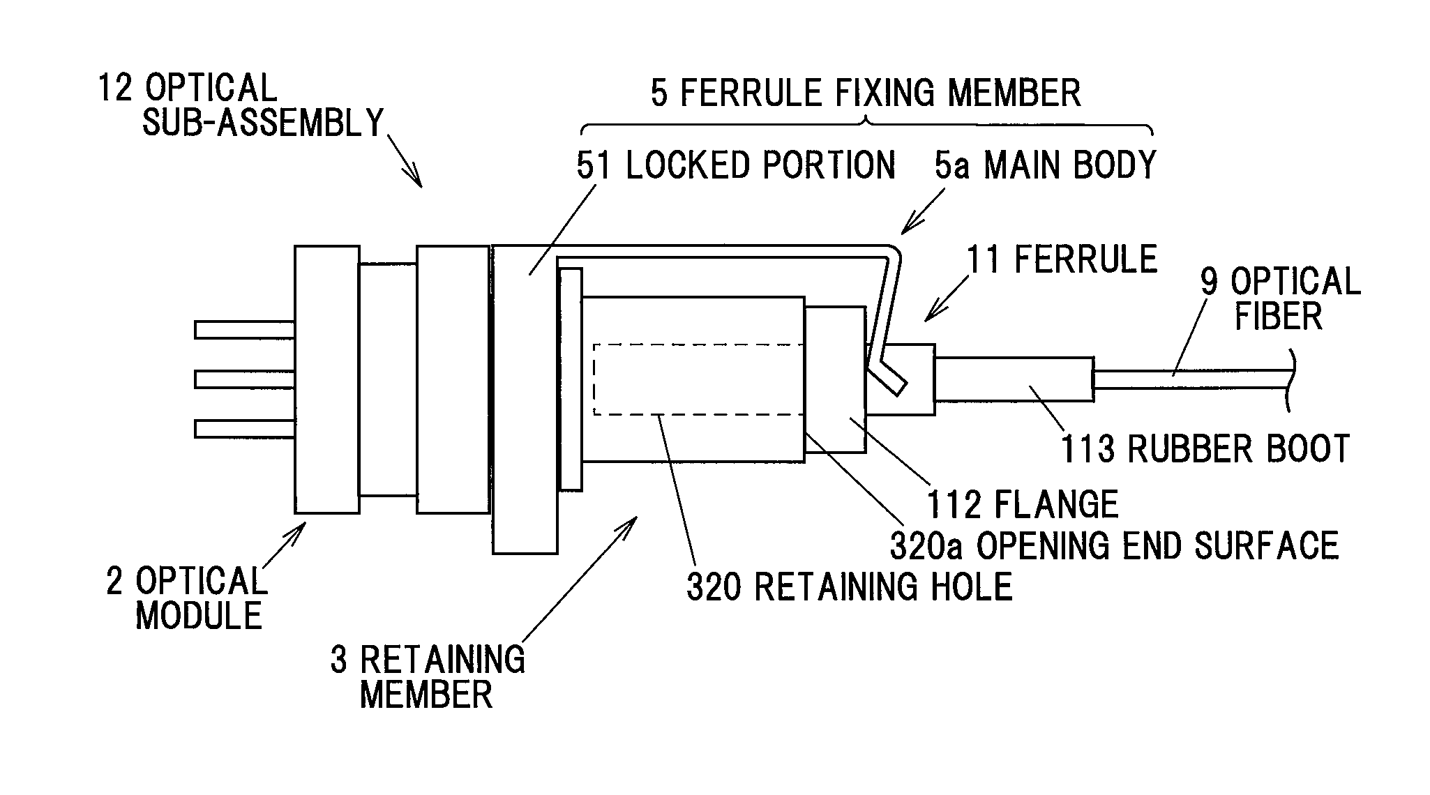
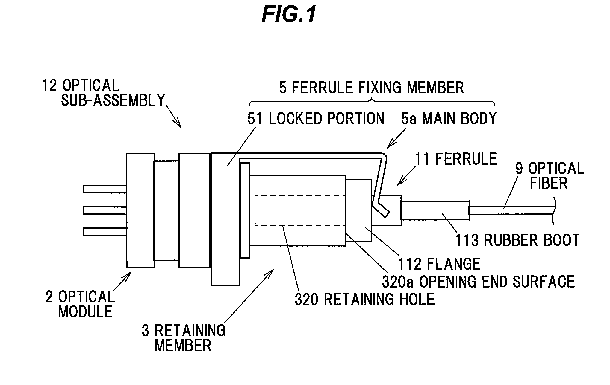
[0026]FIG. 1 is an overall configuration diagram showing a ferrule fixing member 5 in an embodiment of the invention, together with a ferrule 11 and an optical sub-assembly 12 which are fixed by the ferrule fixing member 5. FIG. 2 is a perspective view showing an example configuration of the ferrule 11.
[0027]The ferrule fixing member 5 in the embodiment is a fixing member for fixing the ferrule 11 holding an optical fiber 9 to the optical sub-assembly 12. As shown in FIG. 2, the ferrule 11 has integrally a tubular capillary 111 holding the optical fiber 9 therein and a flange 112 formed so as to protrude outward from the capillary 111. The flange 112 is, e.g., 1.8 mm in width in an extending direction of the optical fiber 9. The optical fiber 9 is led out along a rubber boot 113 which is attached to the capillary 111.
[0028]A transmitter optical sub-assembly (TOSA) or a receiver optical sub-assembly (ROSA) can be used as the optical sub-assembly 12.
[0029]The transmitter optical sub-a...
PUM
 Abstract
Description
Claims
Application Information
 - R&D
- Intellectual Property
- Life Sciences
- Materials
- Tech Scout
- Unparalleled Data Quality
- Higher Quality Content
- 60% Fewer Hallucinations
Browse by: Latest US Patents, China's latest patents, Technical Efficacy Thesaurus, Application Domain, Technology Topic, Popular Technical Reports.
© 2025 PatSnap. All rights reserved.Legal|Privacy policy|Modern Slavery Act Transparency Statement|Sitemap|About US| Contact US: help@patsnap.com