Sterilization apparatus

a technology of sterilization apparatus and liquid sterilizant, which is applied in the direction of machines/engines, process and machine control, instruments, etc., can solve the problems of long time for vaporizing sterilant, negative effect, and inability to reduce particle size well, so as to improve sterilization power and reduce the particle size of liquid sterilizant within a short time, the effect of continuously maintaining the performance of the vacuum pump

Inactive Publication Date: 2014-08-21
HANSHIN MEDICAL
View PDF2 Cites 0 Cited by
  • Summary
  • Abstract
  • Description
  • Claims
  • Application Information

AI Technical Summary

Benefits of technology

[0034]According to the disclosed invention, it is possible to improve sterilizing power by vaporizing a liquid sterilant by using a plurality of cavities to reduce a particle size of the liquid sterilant within a short time.
[0035]According to the disclosed invention, it is possible to continuously maintain performance of a vacuum pump by separately providing an oil tank and the vacuum pump and circulating oil by using an oil pump to prevent condensate water to stay in the vacuum pump over a long period of time.
[0036]Further, it is possible to solve inconvenience about separate discharging of condensate water from the oil tank by a user by automatically discharging condensate water from the oil tank according to a level of oil of the vacuum pump.
[0037]Further, it is possible to solve inconvenience about separate discharging of condensate water by the user by removing condensate water by using a condensate water vaporizer.
[0038]Further, the user can easily recognize whether oil needs to be changed by displaying an oil change message of the vacuum pump on a display unit or transmitting the oil change message to a terminal of the user.

Problems solved by technology

In the method, it takes a long time to vaporize the sterilant in the liquid state, and a particle size is not reduced well.
The generated moisture may be contained in oil of the vacuum pump to cause a negative effect such as a reduction in performance and life-span of the vacuum pump and a reduction in sterilization effect.
As described above, moisture may reduce performance of the sterilizer.

Method used


Image

  • Sterilization apparatus
  • Sterilization apparatus
  • Sterilization apparatus

Examples


Embodiment Construction

[0046]Hereinafter, exemplary embodiments of the present invention will be described in detail with reference to the accompanying drawings.

[0047]A sterilization apparatus according to the present invention includes a sterilant vaporization apparatus and an oil circulating apparatus for vacuum pumps as will be described below. The sterilization apparatus may further include another appropriate constitution sterilizing medical appliances.

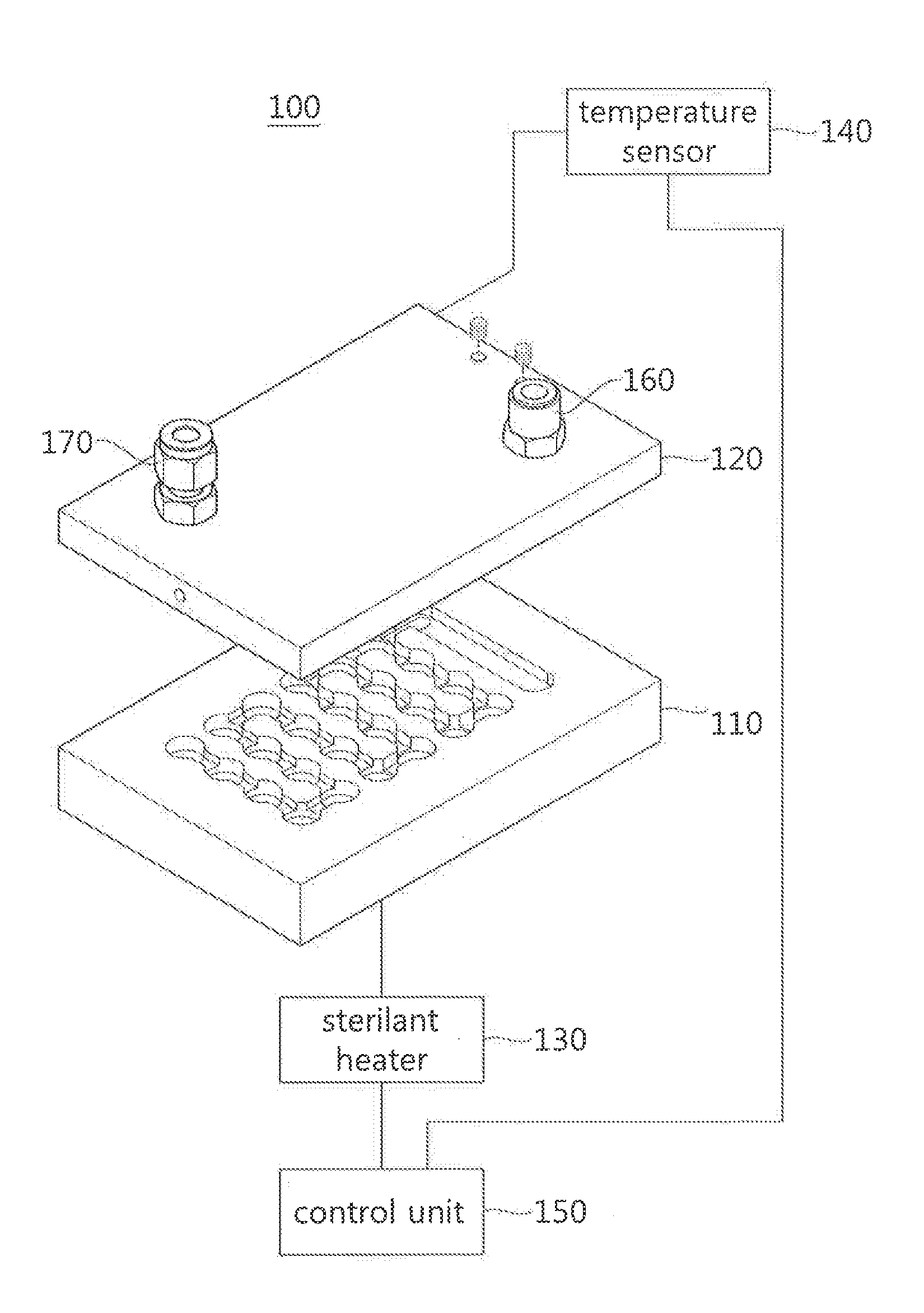
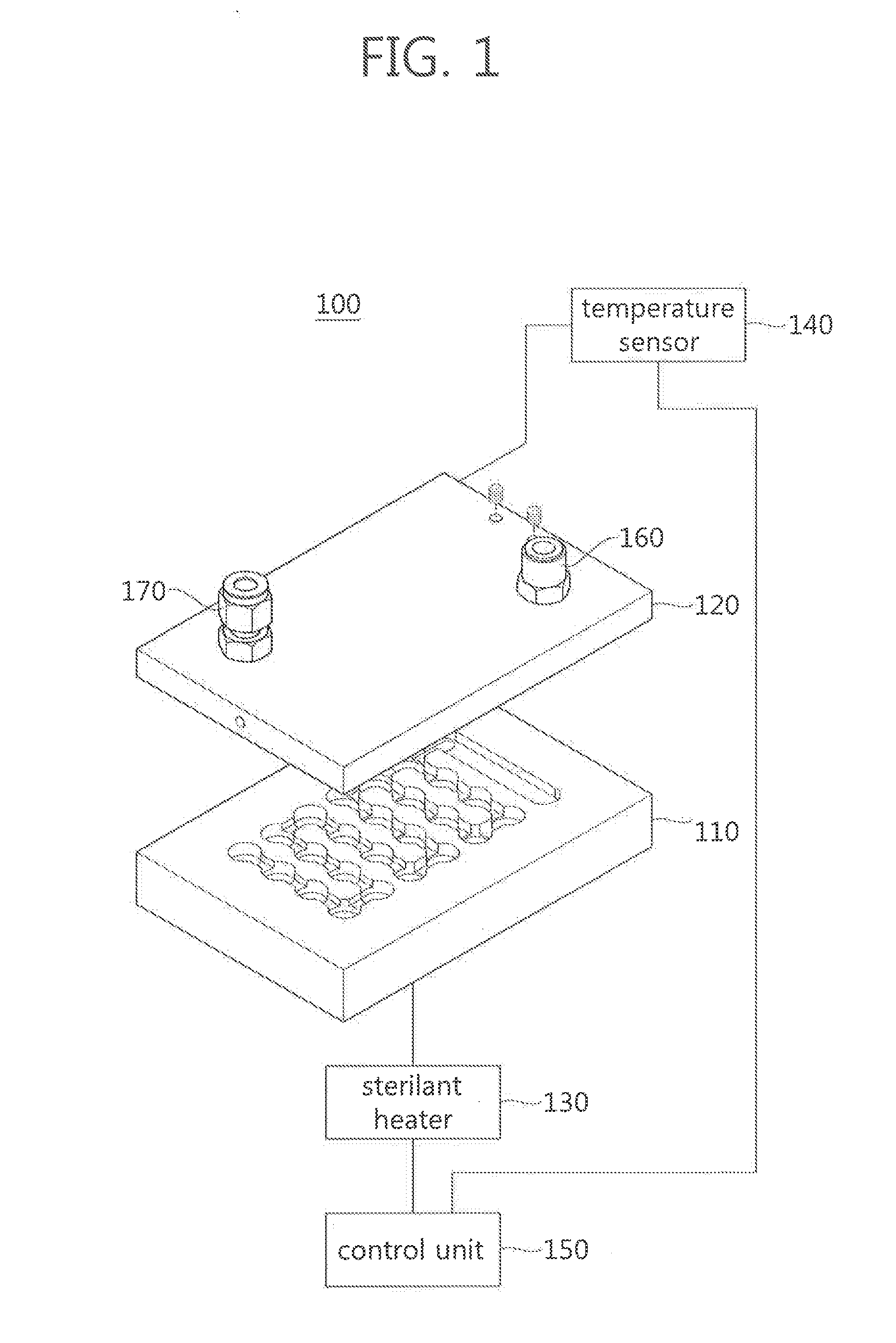
[0048]FIG. 1 is a block diagram showing a sterilant vaporization apparatus relating to an exemplary embodiment of the present invention.

[0049]Referring to FIG. 1, a sterilant vaporization apparatus 100 includes a sterilant vaporizer main body 110, a cover 120, a sterilant heater 130, a temperature sensor 140, and a control unit 150.

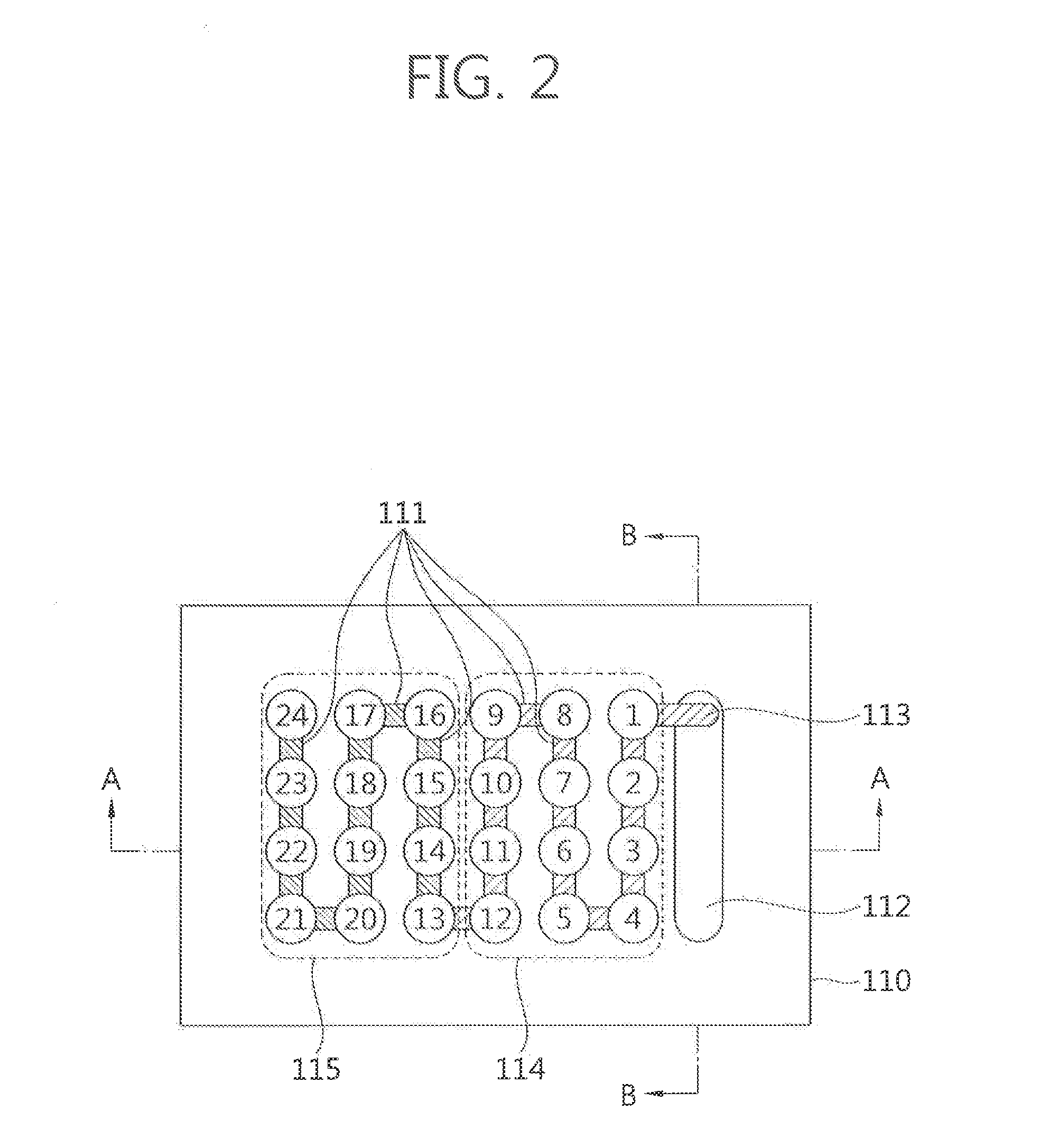
[0050]The sterilant vaporizer main body 110 may be provided with at least two first cavities, a first channel connecting the first cavities to each other, a second cavity containing a sterilant flowing through an inlet, and ...


PUM

PropertyMeasurementUnit
depthsaaaaaaaaaa
depthsaaaaaaaaaa
temperatureaaaaaaaaaa

Abstract

Disclosed is a sterilization apparatus including a sterilant vaporizer main body including at least two first cavities and a first channel connecting the first cavities to each other, a cover including an inlet through which a sterilant flows and mechanically fastened with the sterilant vaporizer main body, and a sterilant heater heating the sterilant vaporizer main body to vaporize the sterilant flowing through the inlet.

Description

RELATED APPLICATIONS[0001]This application claims priority under 35 U.S.C. §119 to Korean Patent Application Number 10-2013-0017960 filed on Feb. 20, 2013, and Korean Patent Application Number 10-2013-0018692 filed on Feb. 21, 2013. The entire contents of the foregoing applications are explicitly incorporated herein by reference.BACKGROUND OF THE INVENTION[0002]1. Field of the Invention[0003]The present invention relates to a sterilant apparatus vaporizing a sterilant in a liquid state to reduce a particle size in a gas state.[0004]2. Discussion of the Related Art[0005]Various types of medical appliances are used after sterilized by a sterilization apparatus to be free from microorganisms present on a surface and an inner cavity thereof. The sterilization apparatus includes a sterilant vaporization apparatus vaporizing a sterilant in a liquid state, and a vacuum pump connected to an inside of a chamber.[0006]In a known method of vaporizing a sterilant in a liquid state, after the st...

Claims


Application Information

Patent Timeline
Patent Type & Authority Applications(United States)
IPC IPC(8): A61L2/26
CPCA61L2/26A61L2/07
Inventor KIM, JUNG YEUL
Owner HANSHIN MEDICAL
Why Eureka
Try Eureka