Clean Air Device and Pass Box Including Ultraviolet Light Emitting Device

a technology of ultraviolet light and vacuum air, which is applied in the direction of space heating and ventilation, lighting and heating apparatus, heating types, etc., can solve the problems of inability to output light having a wavelength other than the range, inability to sterilize lamps, and complicated dispensing methods, etc., to achieve high sterilization power and high sterilization power

Pending Publication Date: 2021-07-29
HITACHI IND EQUIP SYST CO LTD
View PDF5 Cites 0 Cited by
  • Summary
  • Abstract
  • Description
  • Claims
  • Application Information

AI Technical Summary

Benefits of technology

[0007]An object of the present invention is to provide a clean air device or a pass box that uses a semiconductor chip to perform sterilization, the semiconductor chip emitting an ultraviolet ray, in which the intensity of the ultraviolet ray is visualized, so that an article can be installed in a region having high sterilization power.
[0008]In order to solve the above problems, as an example of “a clean air device and a pass box including an ultraviolet light emitting device” of the present invention, there is provided a clean air device or a pass box that includes an ultraviolet light emitting device using a semiconductor chip, in which separately from a semiconductor chip that emits an ultraviolet ray, a semiconductor chip or an indicating lamp that emits visible light is disposed to visualize a strength of an ultraviolet intensity.
[0009]According to the present invention, in the clean air device or the pass box that uses the semiconductor chip to perform sterilization, the semiconductor chip emitting an ultraviolet ray, the intensity of the ultraviolet ray is visualized, so that an article can be installed in a region having high sterilization power.
[0010]Tasks, configurations, and effects other than those described above become apparent from the description of the following embodiments.

Problems solved by technology

A low-pressure mercury lamp is mainly used as the sterilization lamp, and due to containing a very small amount of mercury, the low-pressure mercury lamp may lead to environmental contamination and the disposal method may be complicated.
However, when the semiconductor chip which emits an ultraviolet ray is used as an alternative product, the peak of a wavelength in a deep ultraviolet (UV-C) range, which has a high sterilization effect, can be created, and light having a wavelength other than the range is not output.
Therefore, the light of the sterilization lamp is invisible, and it cannot be determined whether or not the sterilization lamp is turned on and whether or not ultraviolet rays are emitted.

Method used


Image

  • Clean Air Device and Pass Box Including Ultraviolet Light Emitting Device
  • Clean Air Device and Pass Box Including Ultraviolet Light Emitting Device
  • Clean Air Device and Pass Box Including Ultraviolet Light Emitting Device

Examples


first embodiment

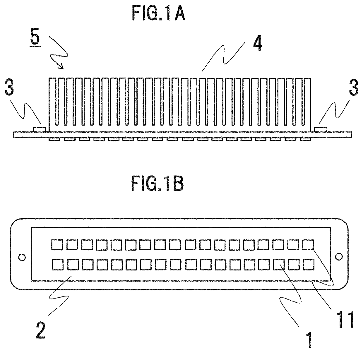
[0022]FIG. 1A is a view seen from a side surface and illustrating one example of an ultraviolet light emitting device of a first embodiment. FIG. 1B is a view seen from a bottom surface side to which semiconductor chips are attached.

[0023]An ultraviolet light emitting device 5 includes a semiconductor chip 1 that emits ultraviolet rays, a semiconductor chip 11 that emits visible light, a substrate 2 on which the semiconductor chip 1 and the semiconductor chip are disposed, a connector 3 to which a wiring for power supply is connected, and a heat radiation fin 4, and is modularized. On one surface of the substrate 2, a plurality of the semiconductor chips 1 that emit ultraviolet rays are disposed in a row, and a plurality of the semiconductor chips that emit visible light are disposed in a row adjacently along the semiconductor chips 1. The heat radiation fin 4 that radiates heat from the semiconductor chips 1 and 11 is provided on an opposite surface of the substrate 2. The semicond...

second embodiment

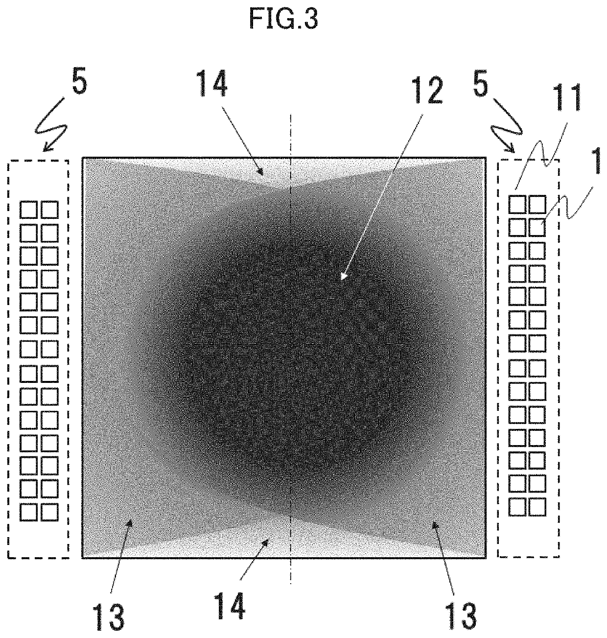
[0033]FIG. 5 shows one example where the strength of the ultraviolet intensity is visualized in warm and cold tones in a second embodiment. Two or more types of the semiconductor chips 11 for visualization having different wavelengths from that of the semiconductor chip 1 (not illustrated) for emission of ultraviolet rays are arranged to create tones. In the drawing, for example, reference sign 11a denotes semiconductor chips that are disposed in central portions in a vertical direction to emit a warm color such as red, and reference sign 11b denotes semiconductor chips that are disposed on both sides in the vertical direction to emit a cold color such as blue. In the drawing illustrating a bottom surface of a work chamber, reference sign 12 denotes a region having a strong ultraviolet intensity and a strong sterilization effect, and the region is displayed in a warm color. Reference sign 13 denotes a region having a medium ultraviolet intensity and a medium sterilization effect, an...

third embodiment

[0036]FIG. 6 illustrates one example of a pass box including an ultraviolet light emitting device of a third embodiment. FIG. 6 illustrates an example where a stainless steel hairline material is used as the material of a bottom surface 15 that is a sterilization surface of the pass box. The stainless steel hairline material is produced by forming a plurality of parallel fine grooves in a surface of a stainless steel plate. A stainless steel hairline direction 17 is set to be parallel to the arrangement of the semiconductor chips 11 for visualization which have an irradiation angle of 120° or less and output visible light having high straightness. Accordingly, as illustrated in FIG. 7, light is reflected by the fine grooves of the hairlines, the color of the visible light of the semiconductor chips 11 for visualization can be seen in a stripe pattern 18, and an ultraviolet irradiation region can be seen at a glance. Since the stripe pattern 18 cannot be seen in a region which cannot...


PUM

PropertyMeasurementUnit
wavelengthaaaaaaaaaa
irradiation angleaaaaaaaaaa

Abstract

In a clean air device or a pass box that includes an ultraviolet light emitting device using a semiconductor chip, separately from a semiconductor chip that emits an ultraviolet ray, a semiconductor chip or an indicating lamp that emits visible light is disposed to visualize a strength of an ultraviolet intensity.

Description

BACKGROUND OF THE INVENTION1. Field of the Invention[0001]The present invention relates to a device that requires sterilization, specifically to a device such as a safety cabinet and an isolator that prevent a hazard which may occur during handling of cells, microorganisms, pathogens, or the like, a device such as a clean cabinet that maintains the cleanness of a work environment, and a device such as a pass box that prevents external contamination when a material is brought into a clean room, in industrial fields such as a regenerative medicine field where cells are cultured or a medical and pharmaceutical field where pathogens are handled and genes are manipulated.2. Description of the Related Art[0002]When cells or microorganisms are handled in research of pathogens or the like, in regenerative medicine, or the like, an isolator or a safety cabinet is used. When it is known in advance that pathogens or the like are not contained, a clean cabinet is used for the purpose of maintai...

Claims


Application Information

Patent Timeline
Patent Type & Authority Applications(United States)
IPC IPC(8): A61L9/20H01L25/075A61L2/10F24F8/22
CPCA61L9/20H01L25/0753A61L2209/12F24F8/22A61L2/10F24F3/16F21V33/00F24F2221/02A61L2202/122A61L2209/14F24F3/163
Inventor KANEKO, TAKESHIMATSUMURA, TAKESHI
Owner HITACHI IND EQUIP SYST CO LTD
Why Eureka
Try Eureka