Variable compression ratio control system

Active Publication Date: 2014-08-28
HYUNDAI MOTOR CO LTD
View PDF4 Cites 3 Cited by
  • Summary
  • Abstract
  • Description
  • Claims
  • Application Information

AI Technical Summary

Benefits of technology

The present invention is about a control system that can adjust the compression ratio in a power transmission part. This can reduce back lash and minimize the amount of movement in the gear coupling. Additionally, the control system can also decrease the amount of force required to rotate the control shaft.

Problems solved by technology

In a case of a spark ignition engine, thermal efficiency may be increased by advance of an ignition timing, but there may be a limitation in the advance of the ignition timing considering abnormal combustion, and the like.
However, the worm and the worm gear have relatively larger back lash than other gear coupling, and an excessive noise and vibration may be generated due to the back lash.
That is, firm gear-coupling of the worm and the worm gear is not easily secured, such that a self-locking function may be weak.
Further, the power transmission of the motor by the worm and the worm gear demands relatively large driving torque, compared to other gear coupling, so that there is a limitation in a decrease in a capacity of the motor.

Method used


Image

  • Variable compression ratio control system
  • Variable compression ratio control system
  • Variable compression ratio control system

Examples


Embodiment Construction

[0026]Reference will now be made in detail to various embodiments of the present invention(s), examples of which are illustrated in the accompanying drawings and described below. While the invention(s) will be described in conjunction with exemplary embodiments, it will be understood that present description is not intended to limit the invention(s) to those exemplary embodiments. On the contrary, the invention(s) is / are intended to cover not only the exemplary embodiments, but also various alternatives, modifications, equivalents and other embodiments, which may be included within the spirit and scope of the invention as defined by the appended claims.

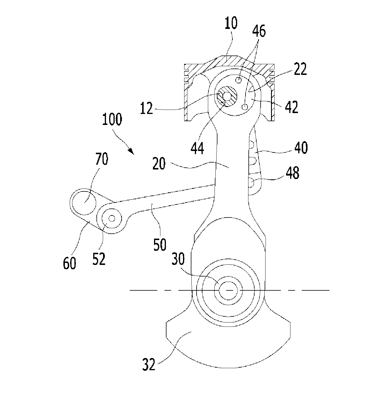
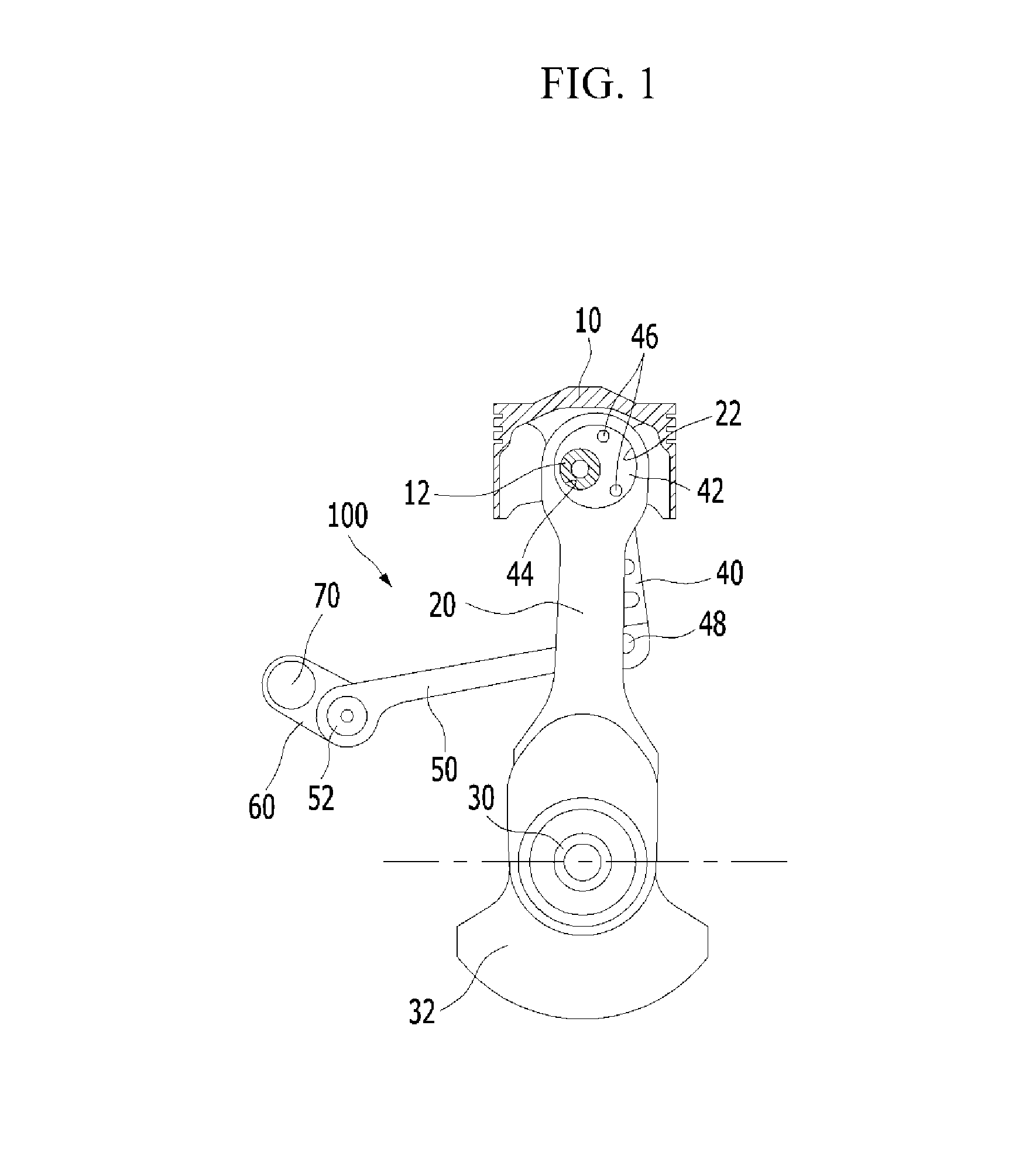
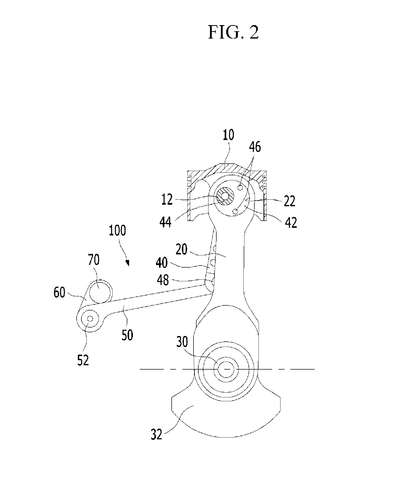
[0027]FIG. 1 is a diagram illustrating a state where a top dead center of a piston moves up according to an operation of a variable compression ratio apparatus and FIG. 2 is a diagram illustrating a state where a top dead center of a piston moves down according to an operation of a variable compression ratio apparatus according to var...


PUM


Abstract

Disclosed is a variable compression ratio control system configured to change a top dead center of a piston in an engine according to an operation state of the engine. The control system may include a motor provided as a power source, a control shaft coupled to the piston, wherein the control shaft changes the top dead center of the piston by a rotation of the control shaft, a driving shaft connected to the motor and to be rotated by the motor, an operation unit movable in a shaft direction of the driving shaft by a rotation of the driving shaft, and an operation link protruding from one portion of an exterior circumferential surface of the control shaft, wherein the operation unit is connected with the operation link so that the operation link rotates the control shaft while the operation unit moves in the shaft direction of the driving shaft.

Description

CROSS-REFERENCE TO RELATED APPLICATION[0001]The present application claims priority of Korean Patent Application Number 10-2013-0019432 filed Feb. 22, 2013, the entire contents of which application are incorporated herein for all purposes by this reference.BACKGROUND OF INVENTION[0002]1. Field of Invention[0003]The present invention relates to a variable compression ratio control system, and more particularly, to a variable compression ratio control system capable of stably controlling a variable compression ratio apparatus changing a compression ratio of mixed gas inside a combustion chamber according to an operation state of an engine.[0004]2. Description of Related Art[0005]In general, thermal efficiency of a heat engine is increased when a compression ratio is high. Here, the compression ratio is a ratio of a volume of gas, which flows in a cylinder, compressed by a piston, and is represented by “cylinder volume / combustion chamber volume at a top dead center of a piston”. That i...

Claims


Application Information

Patent Timeline
IPC IPC(8): F02B75/04
CPCF02B75/04F02B75/045
Inventor WOO, YOONSIKKONG, JIN KOOKLEE, JU HUNLEE, EUN HOLEE, DONG SEOKWOO, SOO HYUNG
Owner HYUNDAI MOTOR CO LTD
Why Eureka
Try Eureka