Pneumatically powered foam sprayer

a foam sprayer and pneumatic technology, applied in the direction of spraying apparatus, liquid spraying apparatus, fire rescue, etc., can solve the problem of reducing the air pressure needed to actuate the control valv

Active Publication Date: 2014-08-28
INNOVATIVE CLEANING EQUIP
View PDF12 Cites 5 Cited by
  • Summary
  • Abstract
  • Description
  • Claims
  • Application Information

AI Technical Summary

Benefits of technology

[0007]A pneumatically powered foam sprayer is provided. The foam sprayer generally includes a spray hose having a spray nozzle, a trigger assembly proximate the spray nozzle, and an air-pressure-actuated control valve that is responsive to the trigger assembly to selectively allow the supply of foam into the spray hose. In one embodiment, the spray nozzle is at all times open to prevent the accumulation of pressurized foam within the spray hose.
[0009]In another embodiment, the air conduit extends longitudinally through a substantial portion of the spray hose. Alternatively, the air conduit extends externally to the spray hose. For example, the air conduit may be joined with and parallel to the spray hose, or it may be separate from and wrapped helically around the exterior of the spray hose. The air conduit is formed from a chemical-resistant material being at least as flexible as the spray hose. In addition, the air conduit includes a laminar outer surface to limit losses in foam consistency during travel of the foam effluent through the spray hose. The air conduit terminates at the trigger assembly, which can include a raised boss for placement of the operator's thumb when foam effluent is desired.
[0011]In these and other embodiments, the pneumatically powered foam sprayer provides an effective, low cost solution to many of the problems associated with existing foam sprayers. In particular, the pneumatically powered foam sprayer can lessen the risk of harm associated with the pressurized buildup of caustic chemicals, while also providing a foam effluent having the desired consistency with little, if any, additional material costs over existing foam sprayers and minimal operator training. Moreover, the pneumatically powered foam sprayer does not require an electrical power supply for operation, lessening the risk of electrical shock and avoiding the problem of corrosion to associated electrical subsystems.

Problems solved by technology

Alternatively, the movement of compressed air can create a vacuum at the opening, in which instance an obstruction can cause a decrease in air pressure to actuate the control valve.

Method used


Image

  • Pneumatically powered foam sprayer
  • Pneumatically powered foam sprayer
  • Pneumatically powered foam sprayer

Examples


Embodiment Construction

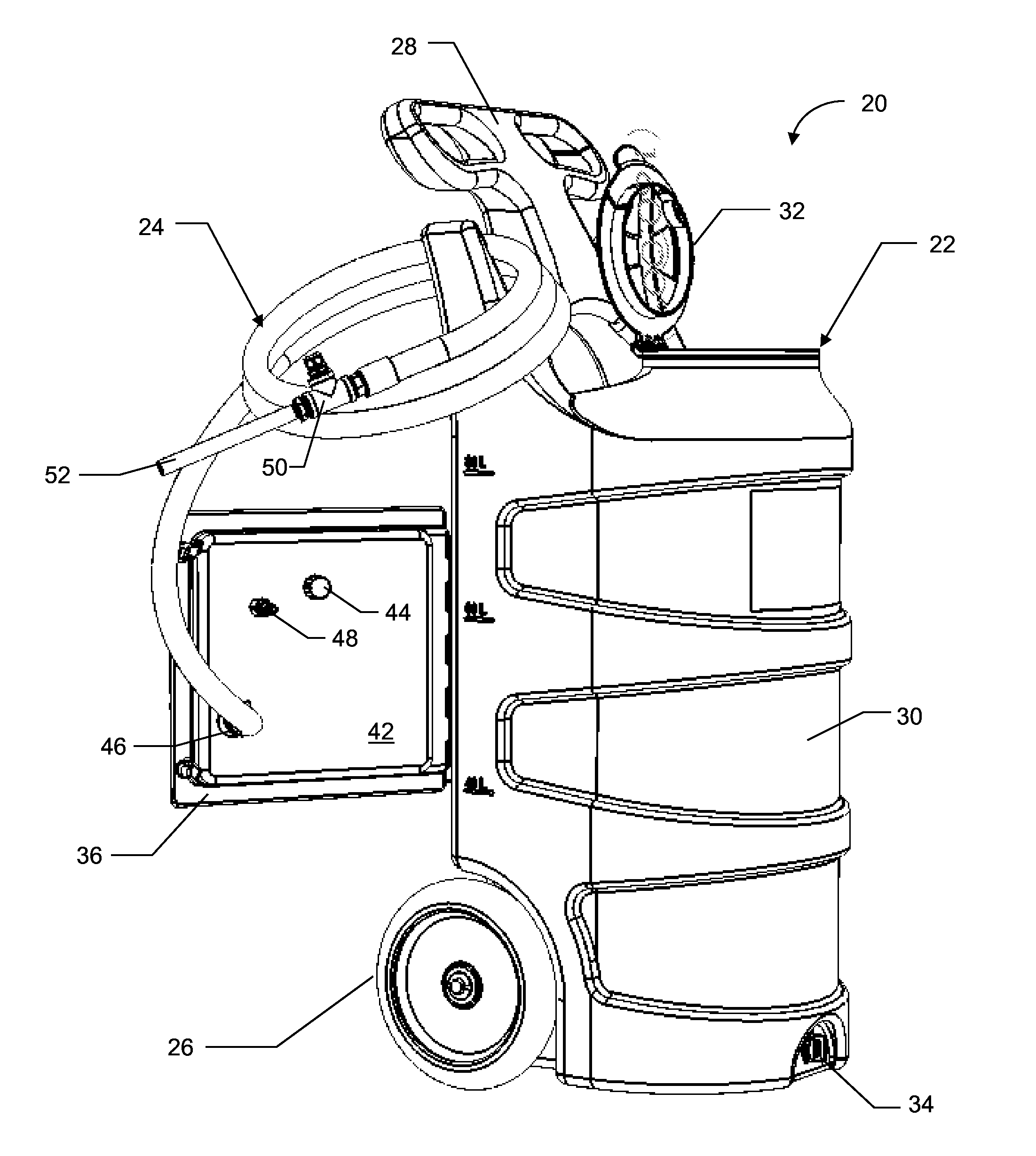
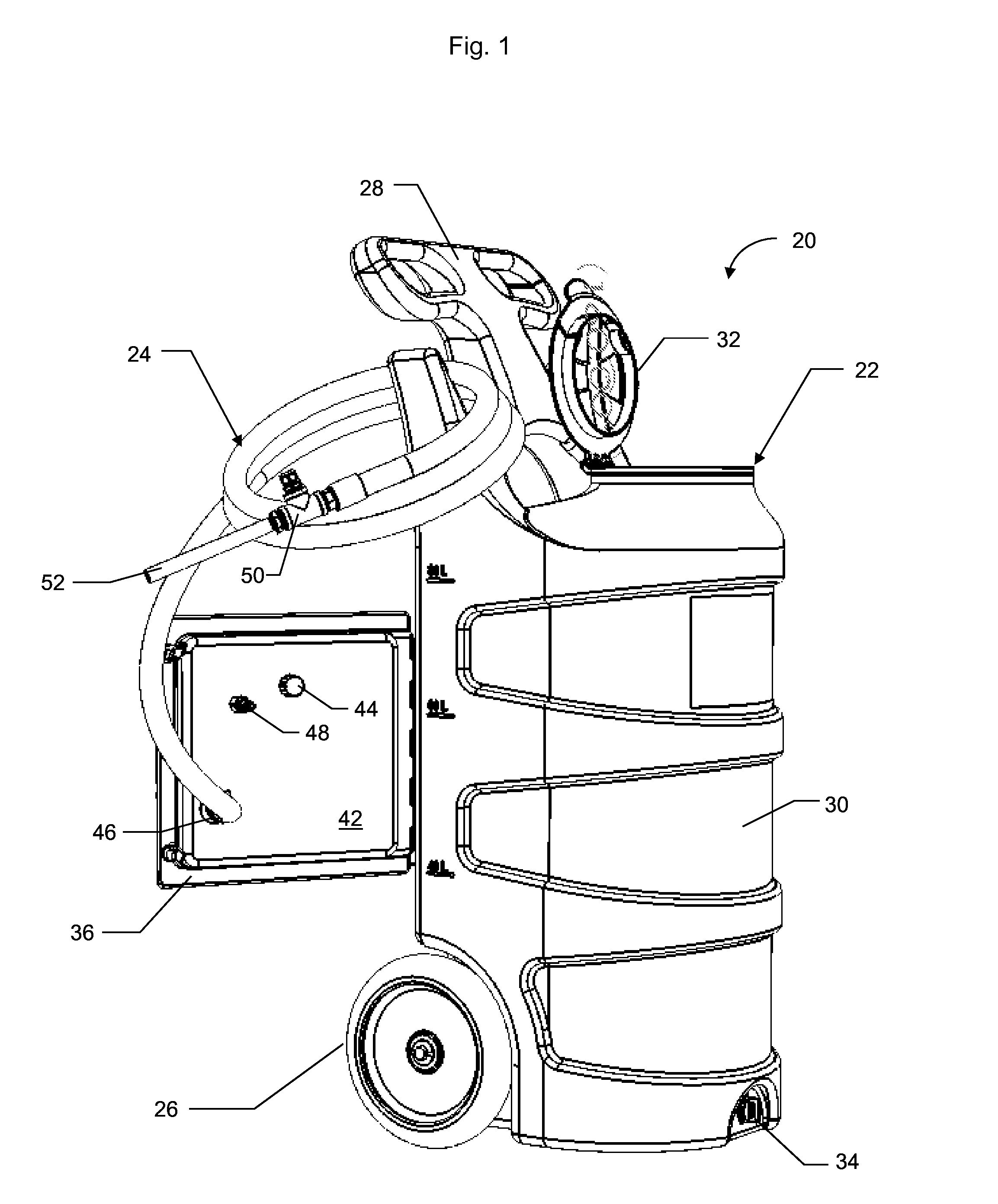
[0021]The invention as contemplated and disclosed herein includes a pneumatically powered foam sprayer adapted to discharge a foam effluent for cleaning or other applications, while minimizing the accumulation of pressurized foam within a spray hose between uses. As set forth more fully below, the foam sprayer includes a control valve to selectively allow the supply of pressurized foam to a spray hose when a foam effluent is desired, and a spray nozzle that remains open both during and between periods of use.

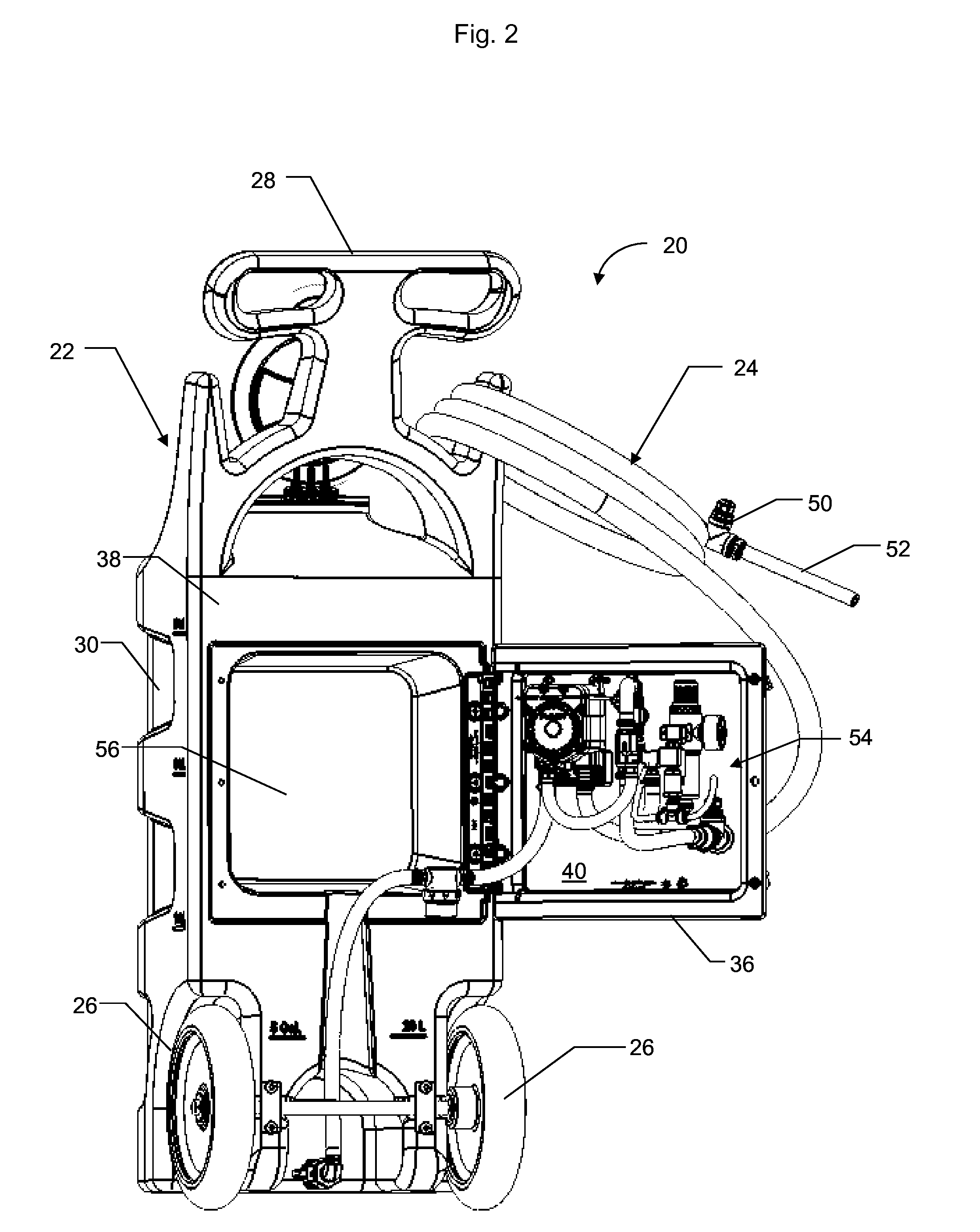
[0022]Referring now to FIG. 1, a pneumatically powered foam sprayer in accordance with one embodiment is illustrated and generally designated 20. The foam sprayer 20 includes a base unit 22 and a spray hose 24. The base unit 22 is depicted as a mobile base unit in the present embodiment, while in other embodiments the base unit 22 remains stationary, optionally being a wall mounted base unit. As shown in FIG. 1, the mobile base unit 22 includes first and second rear wheels 26 an...


PUM


Abstract

A pneumatically powered foam sprayer is provided. The foam sprayer includes a spray hose having a spray nozzle, a trigger assembly proximate the spray nozzle, and a pressure-actuated valve responsive to the trigger assembly. An air conduit extends between the pressure-actuated valve and an opening in the trigger assembly. Obstructing the opening with a hand, a finger or a thumb creates a change of air pressure within the air conduit and actuates the pressure-actuated valve to selectively allow the supply of foam into the spray hose. The air conduit may extends longitudinally through an interior portion of the spray hose, or along an exterior portion of the spray hose, and can include a laminar, chemical-resistant outer surface. An internal pump is powered by compressed air through the pressure-actuated valve, and the spray nozzle remains open both during and between uses to prevent the accumulation of pressurized foam within the spray hose.

Description

BACKGROUND OF THE INVENTION[0001]The present invention relates to powered foam sprayers, and in particular, systems for controlling the discharge of foam effluents from powered foam sprayers for cleaning and for other applications.[0002]Powered foam sprayers have long been recognized as preferred cleaning tools for commercial and industrial cleaning applications. In particular, powered foam sprayers are well suited for coating vertical and elevated surfaces with detergents and other cleaning agents without requiring time-intensive manual brush applications. The foam cleaning agents generally adhere to the surface being cleaned without premature runoff, thereby allowing the cleaning agents added time to more effectively penetrate and sanitize, while also providing the operator with a visual indication of the areas that have already been treated.[0003]Powered foam sprayers often include a pre-mixed cleaning solution for mixing with a supply of compressed air. In these systems, the cle...

Claims


Application Information

Patent Timeline
Patent Type & Authority Applications(United States)
IPC IPC(8): B05B7/00
CPCB05B7/0025A62C31/02A62C31/12B05B7/0093B05B12/085
Inventor JACQUES, NICHOLAS D.LOUWSMA, DEAN
Owner INNOVATIVE CLEANING EQUIP
Why Eureka
Try Eureka