Aerial Photographing System

a technology of aerial photography and camera, which is applied in the field of aerial photography system, can solve the problems that the ground coordinates of the uav cannot be obtained by the gps device in places where radio waves cannot be received, and achieve the effects of high accuracy, high accuracy of photogrammetry and precise position

Active Publication Date: 2014-08-28
KK TOPCON
View PDF3 Cites 69 Cited by
  • Summary
  • Abstract
  • Description
  • Claims
  • Application Information

AI Technical Summary

Benefits of technology

[0012]According to the present invention, the aerial photographing system comprises a flying vehicle being remotely controlled, a camera tiltably supported in any direction via a gimbal, a retro-reflector tilting integrally with the camera, being set in a known relation with the camera and used as an object to be measured, and a total station for tracking the retro-reflector and for measuring position of the retro-reflector. As a result, images can be taken in stable manner regardless of how the posture of the small type flying vehicle is changed, and even under a circumstance where radio waves from artificial satellite cannot be received, ground coordinates of the small type flying vehicle can be measured, and aerial photogrammetry can be performed.
[0013]Further, according to the present invention, in the aerial photographing system, the camera is mounted on a gimbal via a supporting member, and the camera is set up so that an optical axis is directed in vertical direction, and is installed on at least one of the upper end or the lower end of the supporting member. As a result, at least one of the images in vertical and downward direction or in vertical and upward direction is easily acquired.
[0014]Further, according to the present invention, in the aerial photographing system, there is provided a ground base station having an arithmetic device, a storage unit, and a base communication unit, measurement results are transmitted to the ground base station from the total station, wherein the flying vehicle has a flying vehicle communication unit, wireless communication is possible between the flying vehicle communication unit and the ground base communication

Problems solved by technology

However, since the GPS device obtains the ground coordinates by using radio waves from artificial satellite, ground coordinates of the UAV cannot be

Method used


Image

  • Aerial Photographing System
  • Aerial Photographing System
  • Aerial Photographing System

Examples


Embodiment Construction

[0024]Description will be given below on an embodiment of the present invention by referring to the attached drawings.

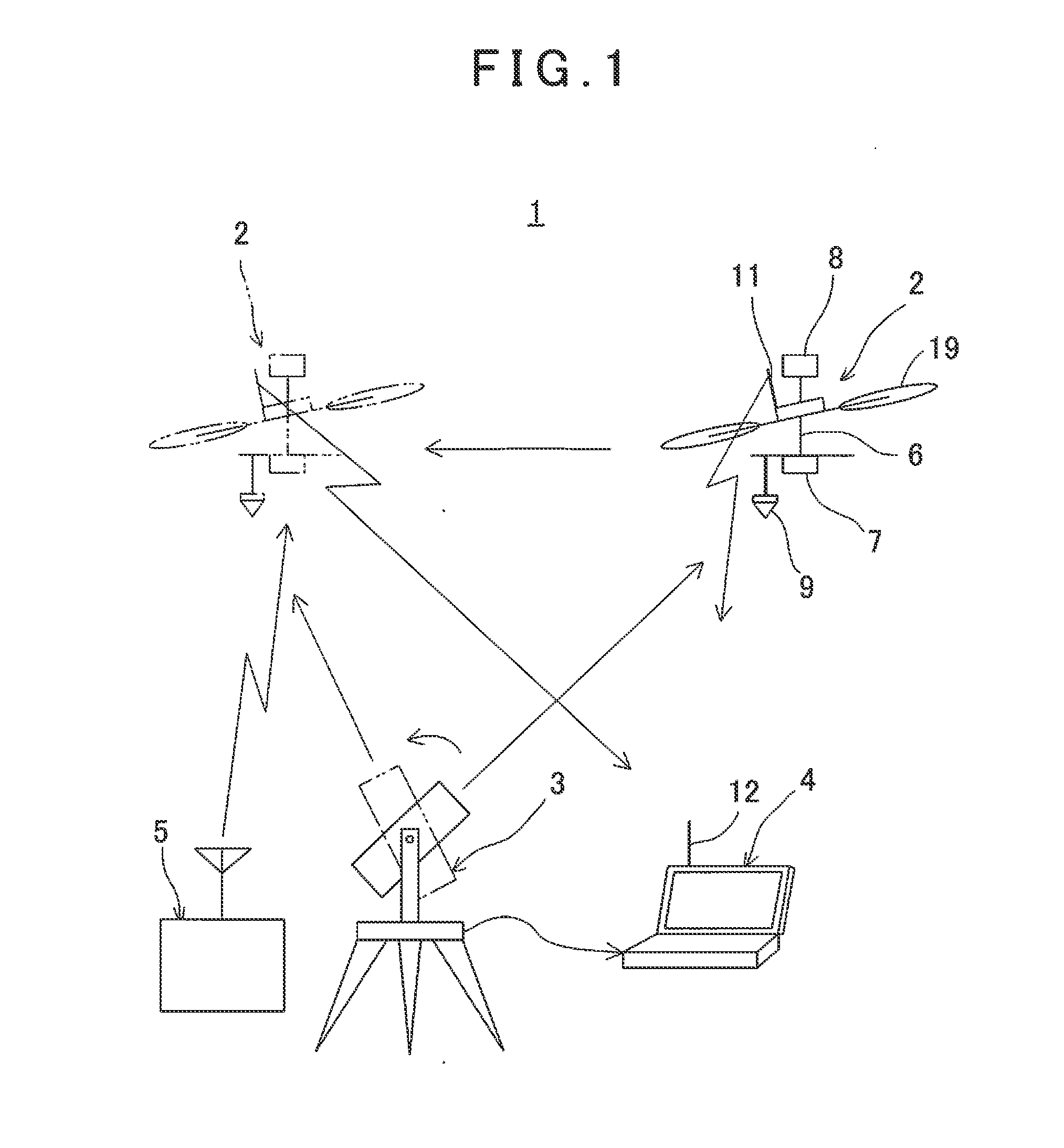
[0025]First, by referring to FIG. 1, description will be given on an aerial photographing system 1 according to the present embodiment.

[0026]The aerial photographing system 1 primarily comprises an aerial photographing device 2, a total station (TS) 3, a ground base station 4, and a remotely controlling device 5.

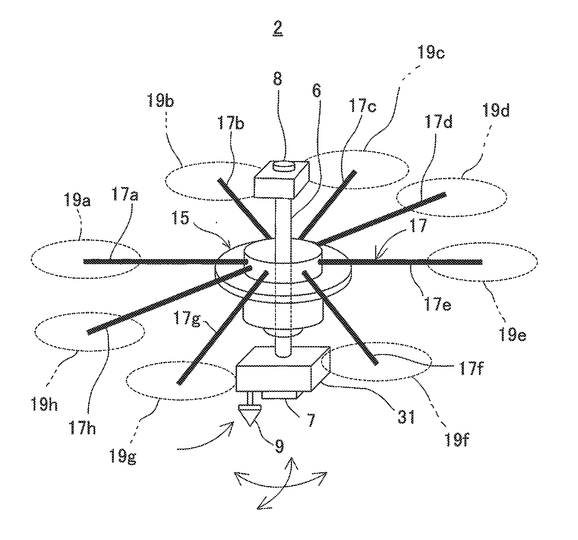
[0027]The aerial photographing device 2 primarily comprises a shaft 6 used as a supporting member supported in vertical direction on a flying vehicle (to be described later) via a gimbal mechanism, a lower camera 7 and an upper camera 8 installed on a lower end and on an upper end of the shaft 6 respectively, a prism 9 installed on lower end of the shaft 6 and used as a retro-reflector integrated with the lower camera 7, and a flying vehicle communication unit 11 to perform communication to and from the ground base station 4. Optical axis of each of the lower...


PUM


Abstract

An aerial photographing system, comprising a flying vehicle being remotely controlled, a camera (7, 8) tiltably supported in any direction via a gimbal (25), a retro-reflector (9) tilting integrally with the camera, being set in a known relation with the camera and used as an object to be measured, and a total station (3) for tracking the retro-reflector and for measuring position of the retro-reflector.

Description

BACKGROUND OF THE INVENTION[0001]The present invention relates to an aerial photographdng system with a camera for photogrammetry installed on a small type flying vehicle.[0002]In recent years, with the progress of UAV (Unmanned Air Vehicle), photogrammetry using UAV has been developed by installing a camera for photogrammetry on UAV.[0003]Normally, a UAV makes flight by tilting its vehicle body in forwarding direction, while the tilting of the vehicle body of the UAV is very likely to be influenced by its speed of propulsion and by wind, and a stability of the tilting is low. On the other hand, in aerial photogrammetry, it is necessary to photograph the images in vertical and downward direction with high precision, and the stability is required on the tilting of the camera.[0004]Further, in aerial photogrammetry, it is necessary to have ground coordinates of the photographing point in order to perform ground orientation (absolute orientation) of an aerial photograph as taken. Conve...

Claims


Application Information

Patent Timeline
IPC IPC(8): B64D47/08H04N7/18
CPCB64D47/08H04N7/185G01C11/02G01C15/00G05D1/0094B64C39/024B64U2101/30
Inventor OHTOMO, FUMIOOTANI, HITOSHIOSARAGI, KAZUKIANAI, TETSUJI
Owner KK TOPCON
Why Eureka
Try Eureka