
Oxidation system and method for cleaning waste combustion flue gas

a technology of oxidation system and flue gas, which is applied in the direction of separation processes, machines/engines, sulfur compounds, etc., can solve the problems of limited cost effectiveness of mechanical and/or chemical processes required to achieve the mandated reduction levels, low to moderate removal efficiency, and fouling of heat transfer surfaces, etc., to achieve efficient and cost effective capture

Inactive Publication Date: 2014-08-28
GENERAL ELECTRIC TECH GMBH
View PDF11 Cites 12 Cited by
  • Summary
  • Abstract
  • Description
  • Claims
  • Application Information

AI Technical Summary

Benefits of technology

The patent describes a system and process for removing sulfur dioxide (SO2) from flue gases produced by waste combustion. The system absorbs sulfur dioxide into a liquid phase and then oxidizes it using a catalyst to form sulfur trioxide (SO32- and SO42-). The replacement of the absorbed sulfur dioxide through this process requires no consumption of sorbent and is highly cost-effective.

Problems solved by technology

A major disadvantage to this second approach is the limited cost effectiveness of the mechanical and / or chemical processes required to achieve the mandated levels of reduction of sulfur oxides and / or other contaminants.
Disadvantages of this method include: fouling of heat transfer surfaces; low to moderate removal efficiencies; poor reagent utilization; and increased particulate loadings in the combustion gases which may require additional conditioning of the gas if an electrostatic precipitator is used for down stream particulate collection.
Disadvantages associated with wet scrubbing processes include: the loss of liquid both to the atmosphere and to the sludge produced in the process; and the economics associated with the construction materials for the absorber module itself and all related auxiliary downstream equipment, such as primary / secondary dewatering and waste water treatment subsystems.
Disadvantages associated with these dry scrubbing processes include: moderate to high gas-side pressure drop across the spray dryer gas inlet distribution device; and limitations on the spray down temperature required to maintain controlled operations.
Other known systems for SO2 removal from flue gas require additional equipment, are very complicated in design and operation, and / or provide a very costly removal method.

Method used


Image

  • Oxidation system and method for cleaning waste combustion flue gas
  • Oxidation system and method for cleaning waste combustion flue gas
  • Oxidation system and method for cleaning waste combustion flue gas

Examples


Embodiment Construction

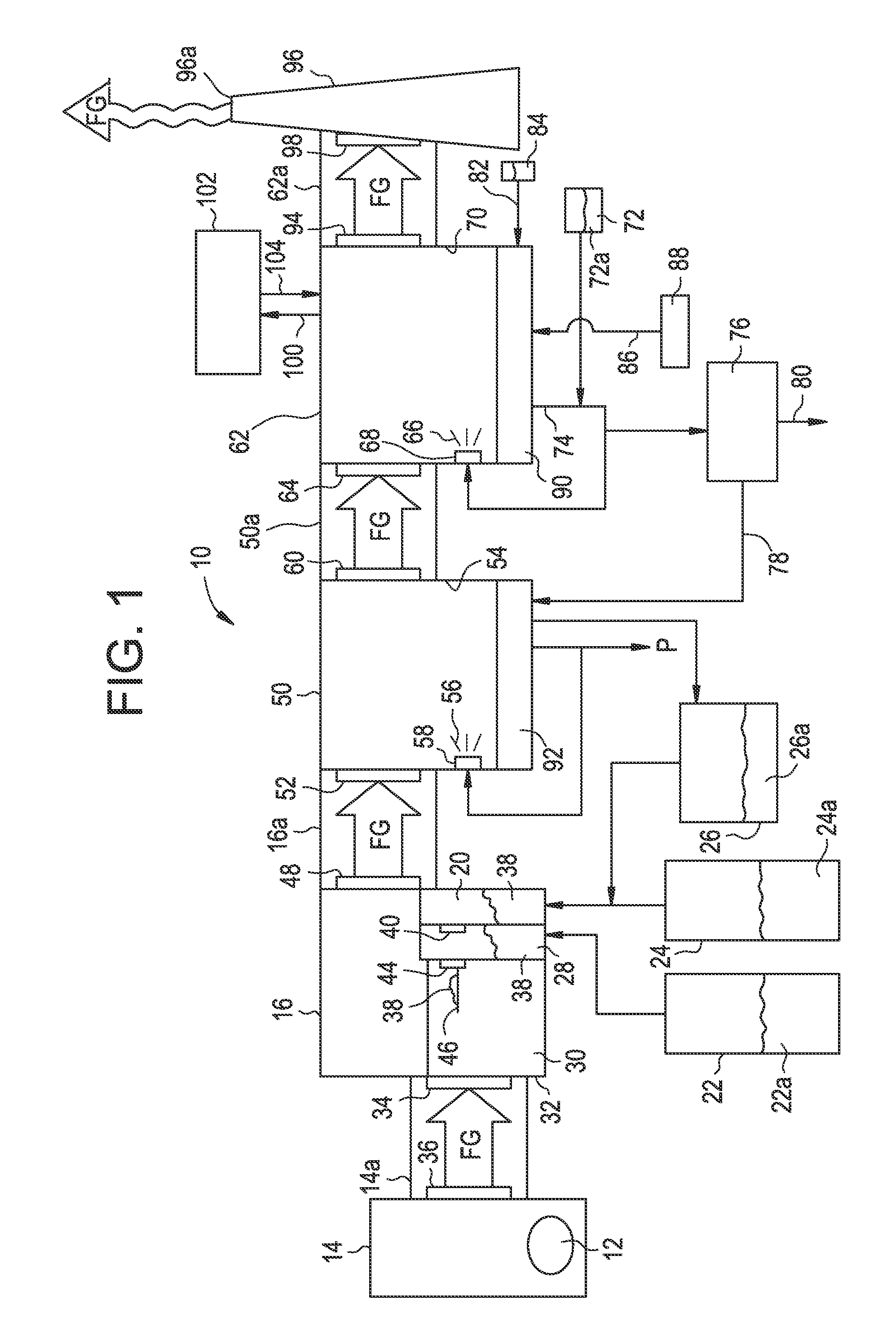
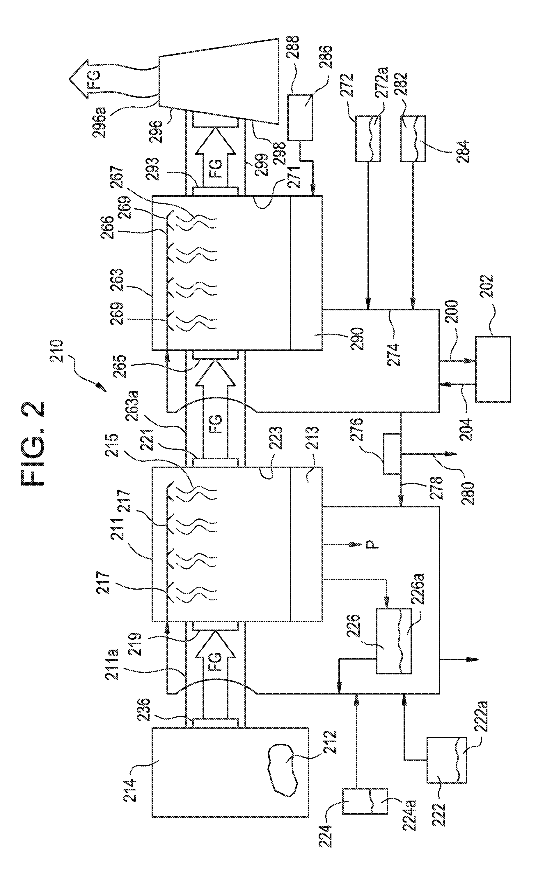
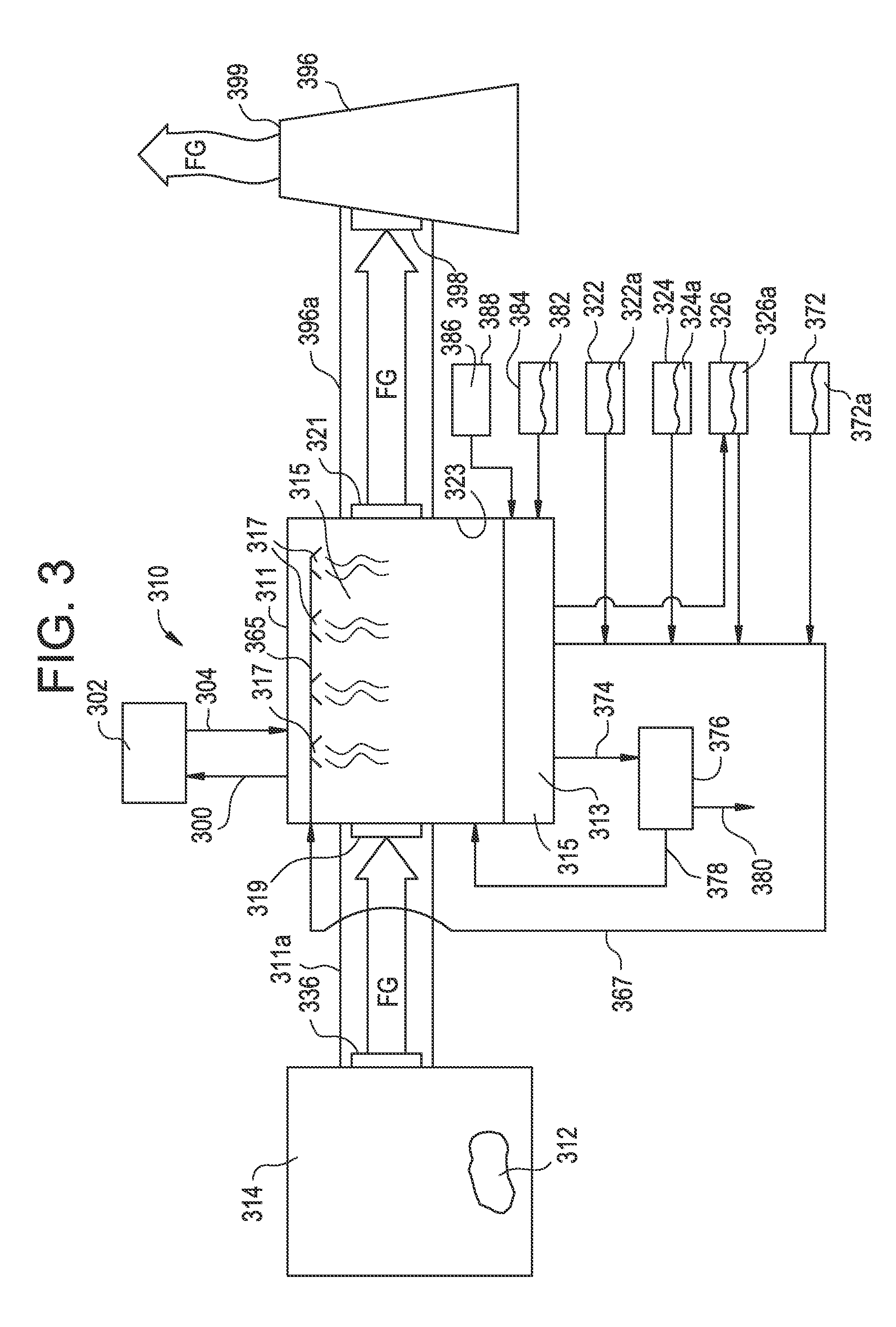
[0018]The combustion of waste produces flue gas comprising SO2. SO2 from the flue gas is poorly absorbed into solution at a pH below 5 due to the dissociation equilibrium as described with regard to Reactions 1 through 3 above. At higher pH, SO2 is dissociated and forms bisulphite, which contributes to a much better absorption. If a bisulphite solution is acidified, the absorbed SO2 desorbs and again escapes the solution. However, if the sulphite in solution, whether dissociated or not, is oxidized to sulphate, i.e., SO42−, it will be dissociated also at low pH since the corresponding sulphuric acid, unlike suphurous acid, is a very strong acid. Hence, the sulphate is “permanently” absorbed and removed from the system sulphite equilibrium.

[0019]With the above in mind, the subject waste combustion flue gas treatment system 10 is described. As best illustrated in FIG. 1, in the subject waste combustion flue gas treatment system 10, waste 12 is combusted in boiler 14. Flue gas “FG” pro...


PUM

PropertyMeasurementUnit
Molar densityaaaaaaaaaa

Abstract

Methods and systems for the removal of SO2 from waste combustion flue gas are described herein. The subject methods and systems entail one step, two steps or three steps to produce cleaned flue gas for release to the atmosphere.

Description

CROSS-REFERENCE TO RELATED APPLICATION[0001]This application claims the benefit of U.S. Provisional Patent Application Ser. No. 61 / 769,982; filed on Feb. 27, 2013, which is incorporated herein by reference in its entirety.FIELD OF THE INVENTION[0002]The present disclosure relates, in general, to the removal of contaminants from flue gas produced by the burning of waste as a combustion fuel and, in particular, to a new and useful method and system for removing SO2 from the flue gas produced by waste fuel combustion.BACKGROUND OF THE INVENTION[0003]In the pollution control field, several approaches are used to remove sulfur oxides and other contaminants from a flue gas produced by the burning of a fossil fuel in order to comply with both European and U.S. emissions requirements.[0004]One approach involves locating and utilizing fossil fuels lower in sulfur content and / or other contaminants. A second approach involves removing or reducing the sulfur content and / or other contaminants in...

Claims


Application Information

Patent Timeline
IPC IPC(8): B01D53/50F01N3/08
CPCB01D53/502F01N3/0814B01D53/501B01D53/8609B01D53/869B01D2251/102B01D2251/11B01D2251/304B01D2255/20738B01D2257/2045B01D2257/406B01D2258/0291
Inventor PERSSON, DANIEL PER NIKLASMARIPUU, MATISWAHN, MARJA
Owner GENERAL ELECTRIC TECH GMBH
Learn More