Heat dissipation structure

Inactive Publication Date: 2014-09-04
ASIA VITAL COMPONENTS SHENZHEN CO LTD
View PDF9 Cites 13 Cited by
  • Summary
  • Abstract
  • Description
  • Claims
  • Application Information

AI Technical Summary

Benefits of technology

The present invention provides an ultra-thin heat dissipation structure that can escape heat leakage and improve heat transfer performance. The structure includes an evaporation section, a condensation section, backflow sections, and a heat insulation coating between them. The heat dissipation structure is designed for limited space and can be used in narrow areas. It is capable of avoiding heat leakage and ensuring continuous vapor-liquid circulation.

Problems solved by technology

The heat generated by the miniaturized components of the electronic apparatus has become a major obstacle to having better performance of the electronic apparatus and system.
The challenge to cooling the product due to increase of thermal flux exceeds the challenge simply caused by increase of total heat.
This is because the increase of thermal flux will lead to overheating at different times with respect to different sizes and may cause malfunction or even burnout of the electronic apparatus.
However, such structures are only applicable to the micro-vapor chamber with thinner upper and lower walls (under 1.5 mm).
However, the vapor chamber has a critical shortcoming that it can hardly transfer the heat to a remote end for dissipating the heat.
The most often seen problem of the loop heat pipe is heat leakage.
This problem is more likely to happen in the narrower flow passages.
This will hinder the condensed working fluid from flowing back to the evaporation section and cause cease of the vapor-liquid circulation of the working fluid in the vapor chamber.
Eventually, the vapor chamber will lose its heat transfer function.

Method used


Image

  • Heat dissipation structure
  • Heat dissipation structure
  • Heat dissipation structure

Examples


Embodiment Construction

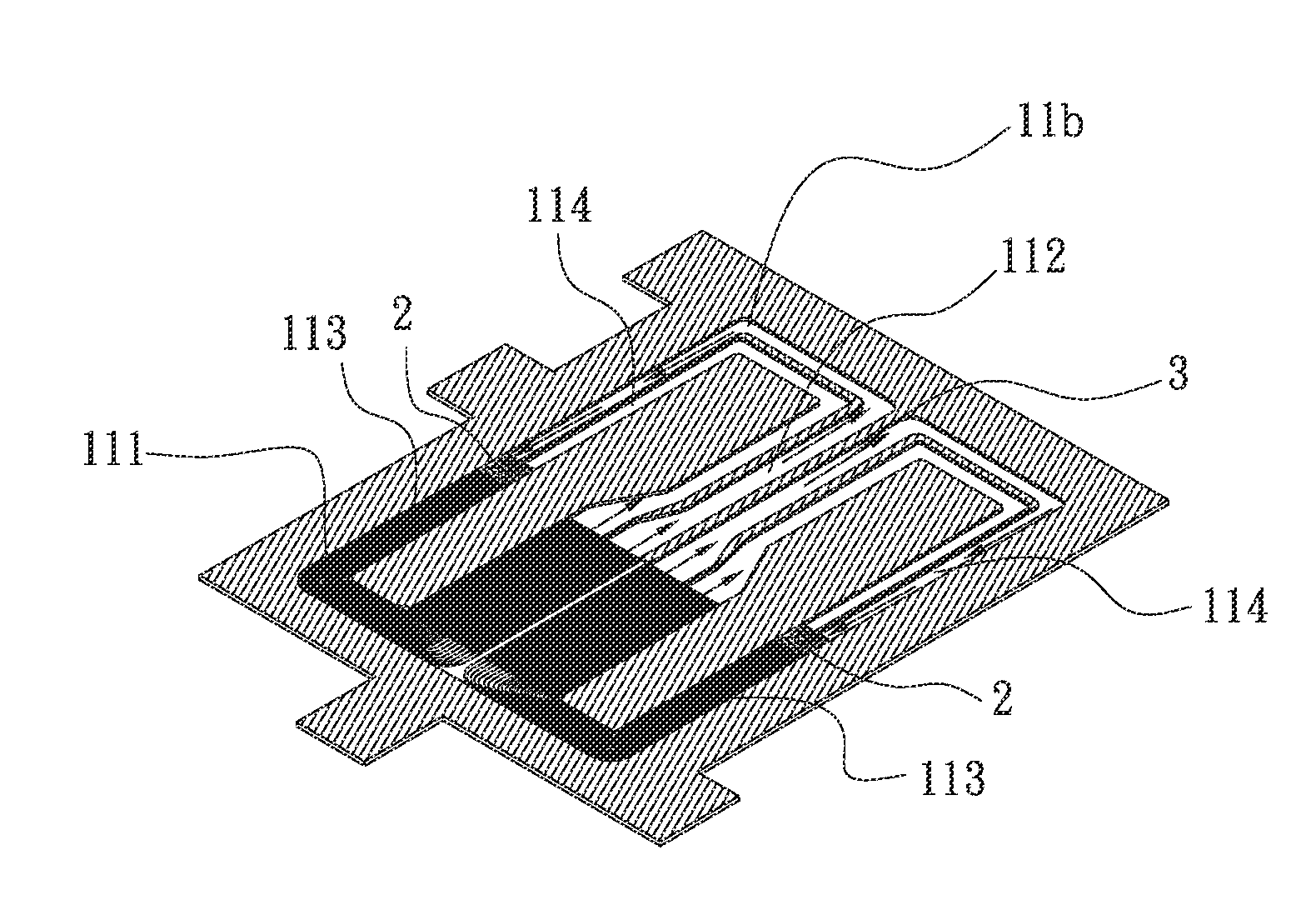
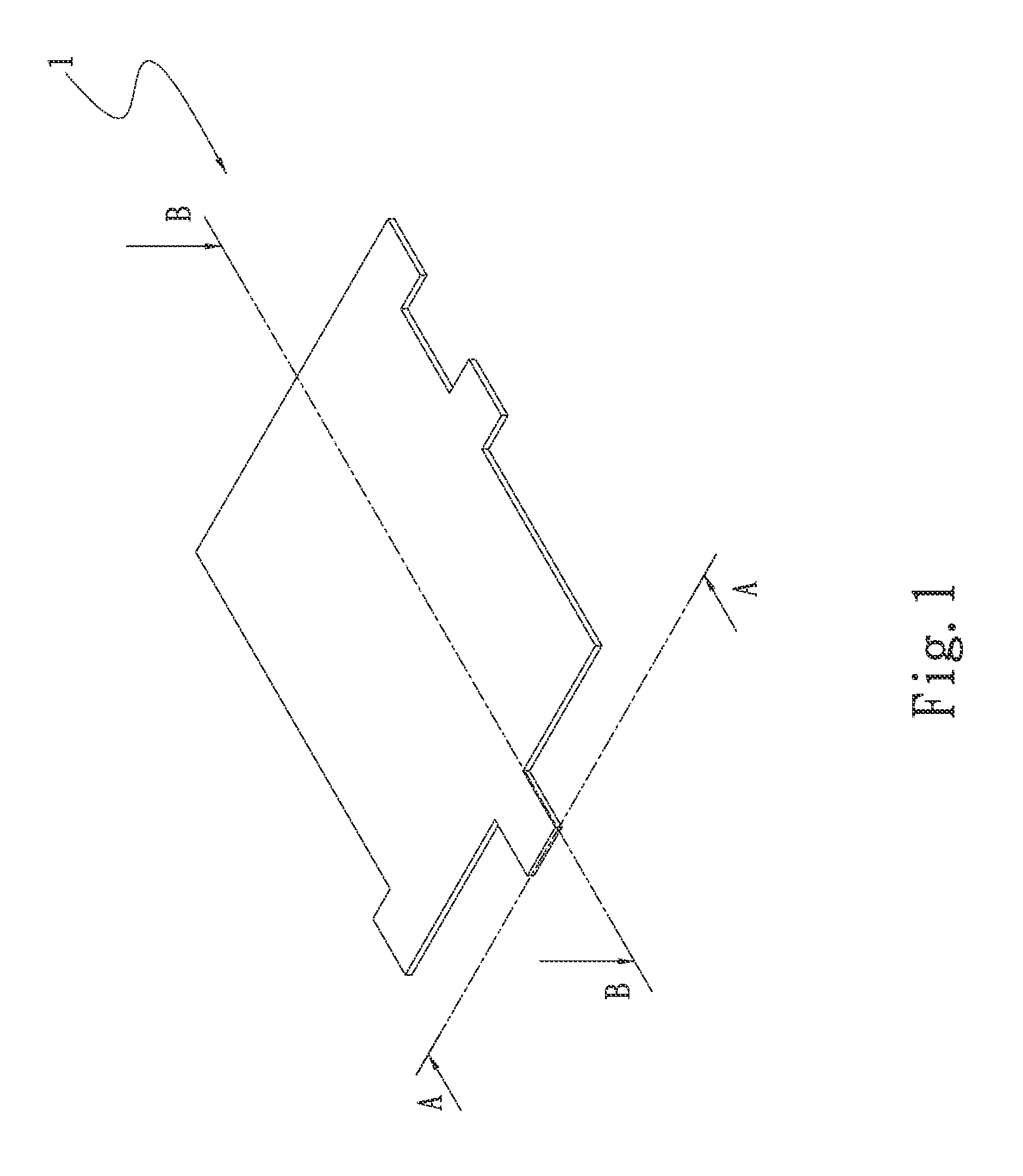
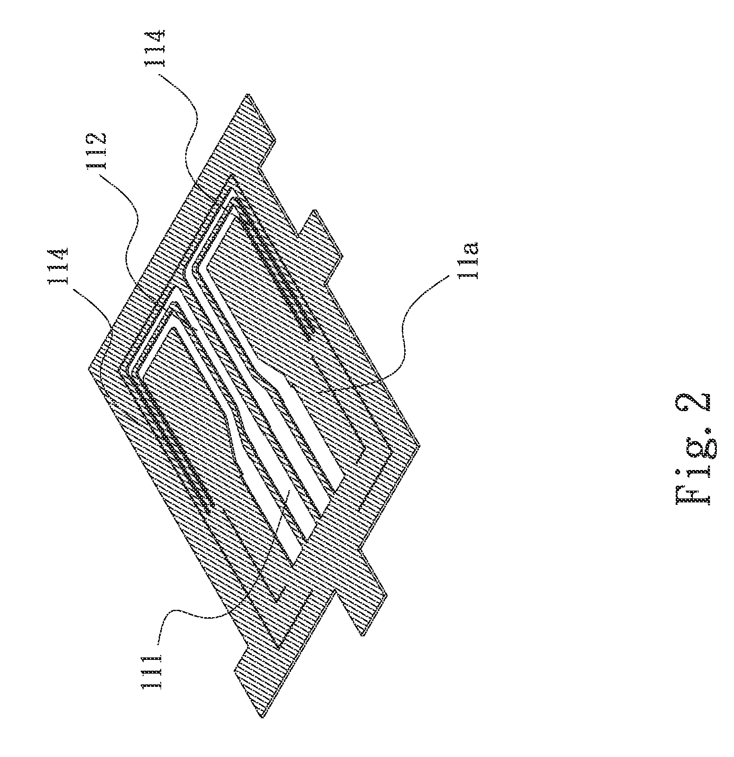
[0019]Please refer to FIGS. 1, 2, 3 and 4. FIG. 1 is a perspective view of a first embodiment of the heat dissipation structure of the present invention. FIG. 2 is a sectional view taken along line A-A of FIG. 1. FIG. 3 is a sectional view taken along line A-A of FIG. 1. FIG. 4 is a sectional view taken along line B-B of FIG. 1. According to the first embodiment, the heat dissipation structure of the present invention includes a main body 1.

[0020]The main body 1 has a chamber 11 having an evaporation section 111, a condensation section 112, a first backflow section 113 and a second backflow section 114. The evaporation section 111 and the condensation section 112 and the first and second backflow sections 113, 114 communicate with each other. A junction between the first and second backflow sections 113, 114 is coated with a heat insulation coating 2. A working fluid 3 is filled in the chamber 11.

[0021]To speak more specifically, the chamber 11 of the main body has a first side 11 a...


PUM


Abstract

A heat dissipation structure includes a main body. The main body has a chamber. The chamber has an evaporation section, a condensation section, a first backflow section and a second backflow section. The evaporation section and the condensation section and the first and second backflow sections communicate with each other. A junction between the first and second backflow sections is coated with a heat insulation coating. A working fluid is filled in the chamber. By means of the heat insulation coating, the heat leakage between the evaporation section and the condensation section can be avoided. In this case, the vapor-liquid circulation of the working fluid in the heat dissipation structure can be continuously successfully performed.

Description

BACKGROUND OF THE INVENTION[0001]1. Field of the Invention[0002]The present invention relates generally to a heat dissipation structure, and more particularly to a heat dissipation structure capable of avoiding heat leakage in the heat dissipation structure so as to ensure stable vapor-liquid circulation of the working fluid in the heat dissipation structure.[0003]2. Description of the Related Art[0004]There is a trend to develop thinner and thinner electronic apparatuses nowadays. The ultra-thin electronic apparatus includes miniaturized components. The heat generated by the miniaturized components of the electronic apparatus has become a major obstacle to having better performance of the electronic apparatus and system. Even if the semiconductors forming the electronic component have been more and more miniaturized, the electronic apparatus is still required to have high performance.[0005]The miniaturization of the semiconductors will lead to increase of thermal flux. The challeng...

Claims


Application Information

Patent Timeline
IPC IPC(8): F28D15/04
CPCF28D15/043F28F13/00F28D15/0233F28D15/0266H01L23/427F28F2270/00H01L2924/0002H01L2924/00
Inventor YANG, HSIU-WEI
Owner ASIA VITAL COMPONENTS SHENZHEN CO LTD
Why Eureka
Try Eureka