Check patentability & draft patents in minutes with Patsnap Eureka AI!

Inductive Power Transfer System and Transmitting and Receiving Devices Thereof

a technology of inductive power transfer and transmitting and receiving devices, which is applied in the direction of transformers, inductances, transportation and packaging, etc., can solve the problems of overheating, affecting the service life of the system, and overheating to a relatively high temperature, so as to overcome the high voltage bias and overheating problems

Inactive Publication Date: 2014-09-04
LUXX LIGHTING TECH TAIWAN
View PDF70 Cites 5 Cited by
  • Summary
  • Abstract
  • Description
  • Claims
  • Application Information

AI Technical Summary

Benefits of technology

The systems described in this patent have the advantage of being able to overcome issues with high voltage bias and overheating that might occur when the distance between the components increases.

Problems solved by technology

However, an increase of the voltage bias at the resonant circuit and the first coil may cause overheating problems.
For example, in the case of a working distance equal to 50 mm and a power transfer of 5 Watts, the voltage bias on the first coil has to be higher than 400V, which may cause overheating to a relatively high temperature, typically above 80 degrees Celsius.
The high voltage bias and overheating issues may raise safety concerns, and also affect the service life of the system.

Method used


Image

  • Inductive Power Transfer System and Transmitting and Receiving Devices Thereof
  • Inductive Power Transfer System and Transmitting and Receiving Devices Thereof
  • Inductive Power Transfer System and Transmitting and Receiving Devices Thereof

Examples


Embodiment Construction

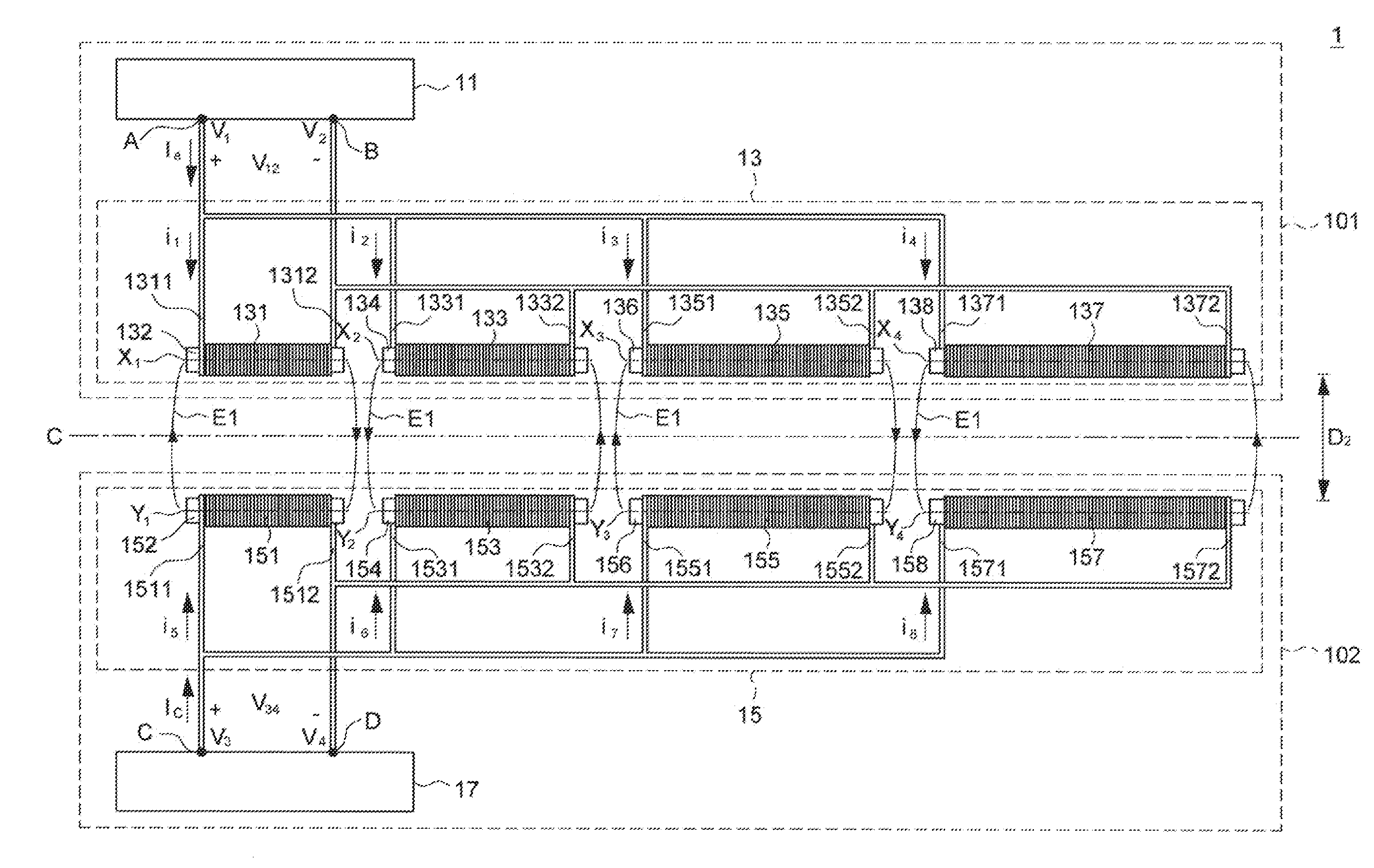
[0018]FIG. 1 is a schematic view illustrating an embodiment of a contactless power transfer system 1. The term “contactless” as used herein means that the power transfer system can transfer power from a transmitting device to a receiving device without physical contact between conductive electrodes. The power transfer system 1 can include a transmitting device 101 and a receiving device 102. The transmitting device 101 can transfer power to the receiving device 102 through inductive coupling. The transmitting device 101 can include a power source circuit 11 and an energizing coil assembly 13. The receiving device 102 can include an energizing coil assembly 15 and an electric load 17. The two energizing coil assemblies 13 and 15 may be arranged approximately symmetric at two sides of a lengthwise axis C. The power source circuit 11 can transfer power to the electric load 17 through inductive coupling between the two energizing coil assemblies 13 and 15.

[0019]The energizing coil assem...


PUM


Abstract

A contactless power transfer system can respectively connect multiple conductive coils in parallel between the power source circuit of a transmitting device and the electric load of a receiving device, and can wind the conductive coils in successively alternating directions. Advantages of the contactless power transfer system include the ability to prevent issues related to overheating and excessive power voltages on the conductive coils, which may occur in applications requiring greater working distances between the energizing coil assemblies.

Description

CROSS-REFERENCE TO RELATED APPLICATION[0001]This application claims priority to Taiwan Patent Application No. 102107304 filed on Mar. 1, 2013, which is incorporated herein by reference.BACKGROUND[0002]1. Field of the Invention[0003]The present invention relates to inductive power transfer systems.[0004]2. Description of the Related Art[0005]Electric appliances are widely present in modern living surroundings. While cable connection is conventionally used to power electric appliances of bigger sizes (such as desktop computers, television sets and the like), battery cells may be used for small and portable devices such as mobile phones, portable media players, wireless pointing devices and the like.[0006]In order to facilitate access to the electric power in a safe manner, one known approach consists in transferring electric power “wirelessly” (i.e., without physical contact between connection electrodes) through inductive coupling between conductive coils. In such systems, a first co...

Claims


Application Information

Patent Timeline
IPC IPC(8): H01F38/14H02J7/02
CPCH02J7/025H01F38/14H02J50/402H02J50/10H02J50/005
Inventor LIAO, KO-TINGWU, TZONG-DARCHANG, JU-CHIAO
Owner LUXX LIGHTING TECH TAIWAN
Features
  • R&D
  • Intellectual Property
  • Life Sciences
  • Materials
  • Tech Scout
  • Unparalleled Data Quality
  • Higher Quality Content
  • 60% Fewer Hallucinations
Learn More