
Light emission module

Inactive Publication Date: 2014-09-04
PANASONIC INTELLECTUAL PROPERTY MANAGEMENT CO LTD
View PDF14 Cites 18 Cited by
  • Summary
  • Abstract
  • Description
  • Claims
  • Application Information

AI Technical Summary

Benefits of technology

The patent describes a way to make sure that light-emitting elements on a computer chip use less power than those on the edges. This results in a cooler middle section of the chip and reduces the temperature rise there. overall, the invention helps to make the chip more uniform in temperature and saves energy.

Problems solved by technology

Thus, in each of the one or more of the light-emitting element blocks belonging to the second block group and additionally including the one or more light-emitting elements connected in parallel, a flowing current and power consumption increase.
Thus, in each of one or more of the light-emitting element blocks belonging to the second block group and including a smaller number of light-emitting elements connected in series, an operating current and power consumption increase.
In each of the one or more light-emitting element blocks belonging to the first block group, power consumption becomes relatively low.
Connecting the resistor, however, results in power loss.

Method used


Image

  • Light emission module
  • Light emission module
  • Light emission module

Examples


embodiments

Embodiment 1

[0051]The following describes a light-emitting module, a lamp unit, and a lighting device pertaining to Embodiment 1 with reference to the drawings.

[0052]1>

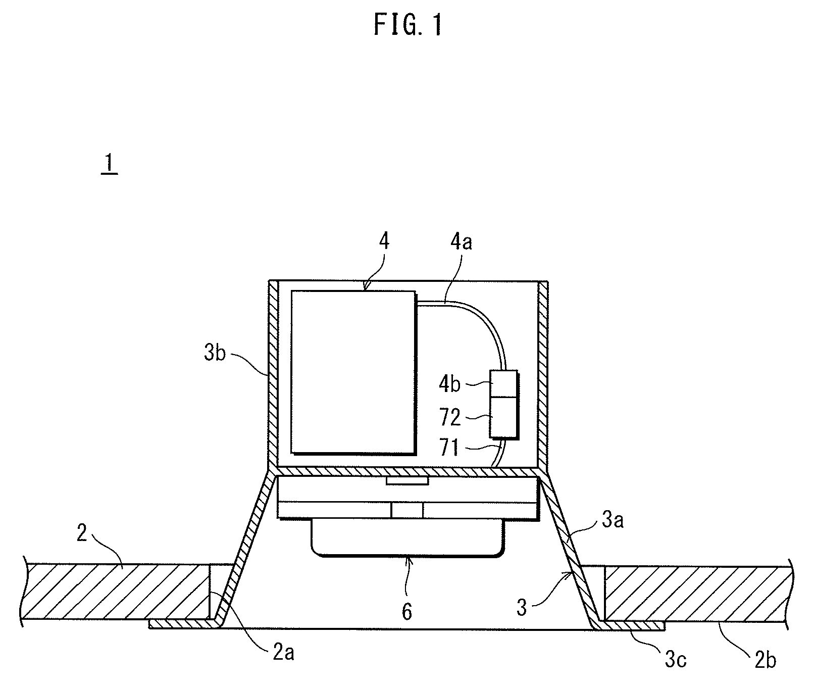
[0053]FIG. 1 is a sectional view of a lighting device 1 incorporating a light-emitting module 10 pertaining to an embodiment.

[0054]The lighting device 1 is a downlight embedded in the ceiling 2, and includes a fixture 3, a circuit unit 4, a dimming unit 5, and a lamp unit 6.

[0055]The fixture 3 is made of metal, and has a lamp housing 3a, a circuit housing 3b, and an outer flange 3c. The lamp housing 3a has a bottomed cylindrical shape. The lamp unit 6 is detachably mounted inside the lamp housing 3a. The circuit housing 3b extends from the bottom of the lamp housing 3a, and houses the circuit unit 4. The outer flange 3c is annular in shape, and extends outward from an aperture of the lamp housing 3a.

[0056]The fixture 3 is fixed to the ceiling 2 in a state where the lamp housing 3a and the circuit housing 3b are embed...

embodiment 1

Modifications of Embodiment 1

[0147]In Embodiment 1, each of the one or more light-emitting element blocks belonging to the first block group includes only blue light-emitting elements 12B. Each of the one or more light-emitting element blocks belonging to the first block group, however, may include one or more red light-emitting elements 12R. In this case, each of one or more of the light-emitting element blocks belonging to the second block group is set to include a greater number of red light-emitting elements 12R than each of the one or more light-emitting element blocks belonging to the first block group, so that each of the one or more of the light-emitting element blocks belonging to the second block group consumes more power than each of the one or more light-emitting element blocks belonging to the first block group.

[0148]The combination of colors of light emitted from the light-emitting elements is not limited to blue and red. By using light-emitting elements emitting light...

embodiment 2

Modifications of Embodiment 2

[0167]In Embodiment 2, each of the one or more light-emitting element blocks belonging to the first block group includes only small light-emitting elements 12. Each of the one or more light-emitting element blocks belonging to the first block group, however, may include one or more large light-emitting elements 12. In this case, each of one or more of the light-emitting element blocks belonging to the second block group is set to include a greater number of large light-emitting elements 12 than each of the one or more light-emitting element blocks belonging to the first block group, so that each of the one or more of the light-emitting element blocks belonging to the second block group consumes more power than each of the one or more light-emitting element blocks belonging to the first block group.

Embodiment 3

[0168]In a light-emitting module 120 in the present embodiment, in each of one or more of the light-emitting element blocks belonging to the second...


PUM


Abstract

In a mounting area, a plurality of light-emitting elements are two-dimensionally mounted, and light-emitting elements are connected in series in each of light-emitting element blocks. The light-emitting element blocks) are connected in parallel by wires. The light-emitting element blocks located in a middle portion each include only blue light-emitting elements. On the other hand, the light-emitting elements located above the light-emitting element blocks and the light-emitting element blocks located below the light-emitting element blocks include one or more light-emitting element blocks each including not only blue light-emitting elements but also one or more red light-emitting elements.

Description

TECHNICAL FIELD[0001]The present invention relates to a light-emitting module including light-emitting elements, such as LEDs, two-dimensionally mounted on a substrate.BACKGROUND ART[0002]Light-emitting modules including LEDs are widely used as backlights in lighting devices and display devices, as they have advantages of having long lives, being compact, having high luminous efficiency, and emitting bright light. As a light-emitting module for use in large-capacity lighting devices, such as downlights, a light-emitting module that includes a great number of LED chips two-dimensionally mounted on a substrate and covered with sealing materials has been developed.[0003]As for such a light-emitting module that includes a great number of LED chips two-dimensionally mounted, the light-emitting device disclosed in Patent Literature 1 has a balanced overall circuit structure by setting the number of LED chips in each of rows connected in parallel to be the same.[0004]In the light-emitting ...

Claims


Application Information

Patent Timeline
IPC IPC(8): F21K99/00H05B44/00
CPCF21K9/30F21S8/026H01L25/0753H01L2924/0002F21Y2105/10F21Y2115/10F21Y2113/13F21K9/64H05B45/40H05B45/00H05B45/56H01L2924/00Y02B20/30
Inventor ABE, MASUMIWADA, YASUFUMIOGATA, TOSHIFUMISUGIURA, KENJI
Owner PANASONIC INTELLECTUAL PROPERTY MANAGEMENT CO LTD
Features
  • Generate Ideas
  • Intellectual Property
  • Life Sciences
  • Materials
  • Tech Scout
  • Unparalleled Data Quality
  • Higher Quality Content
  • 60% Fewer Hallucinations
Learn More