Electric vacuum pump

Inactive Publication Date: 2014-09-04
AISAN IND CO LTD
View PDF0 Cites 761 Cited by
  • Summary
  • Abstract
  • Description
  • Claims
  • Application Information

AI Technical Summary

Benefits of technology

[0034]The electric vacuum pump according to the invention can achieve reduced si

Problems solved by technology

Furthermore, for a hybrid vehicle, an electric vehicle, or a vehicle with an idling stop functi

Method used


Image

  • Electric vacuum pump
  • Electric vacuum pump
  • Electric vacuum pump

Examples


Embodiment Construction

[0055]A detailed description of a preferred embodiment of an electric vacuum pump embodying the present invention will now be given referring to the accompanying drawings. In the present embodiment, the electric vacuum pump of the invention applied to a brake system will be explained.

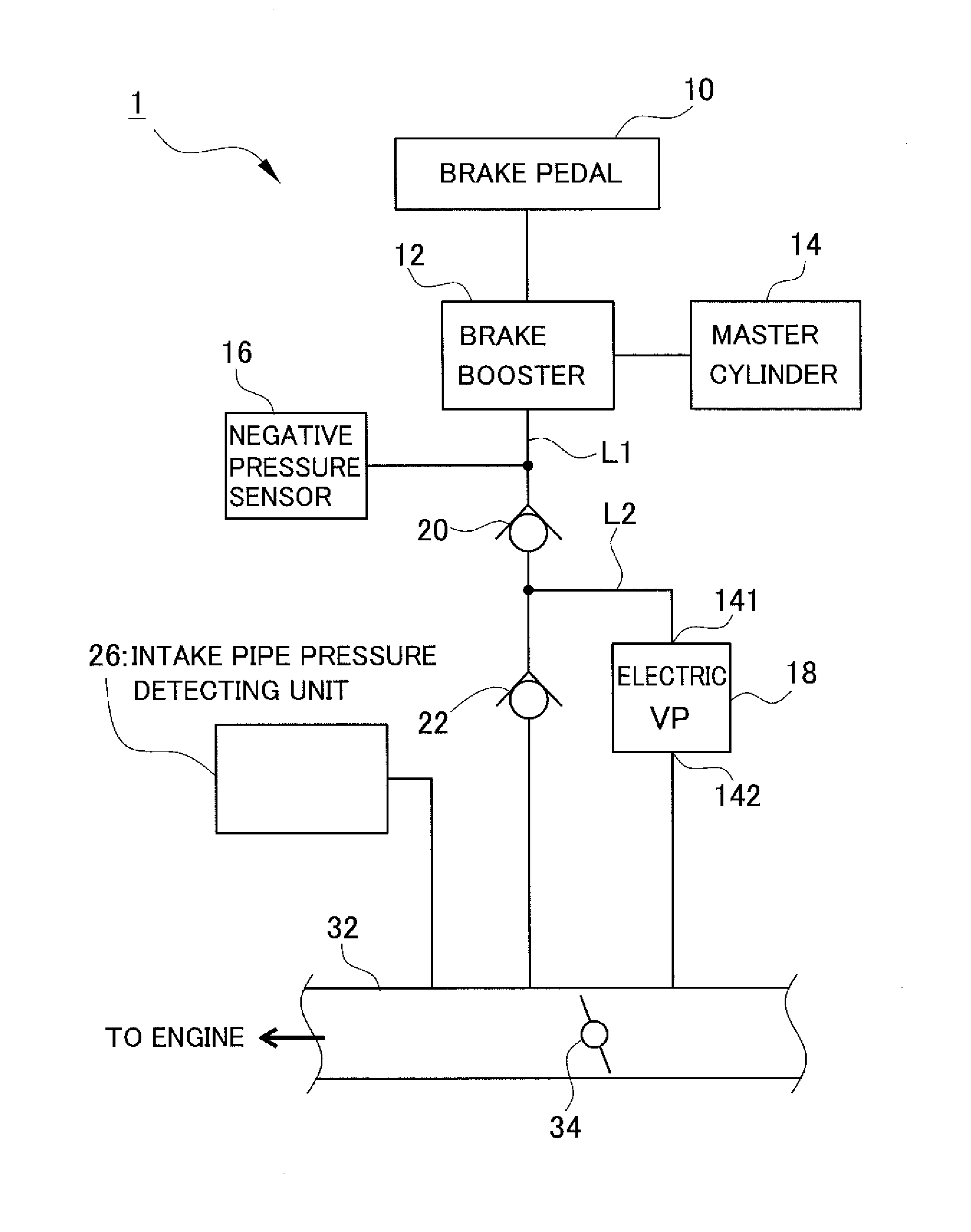
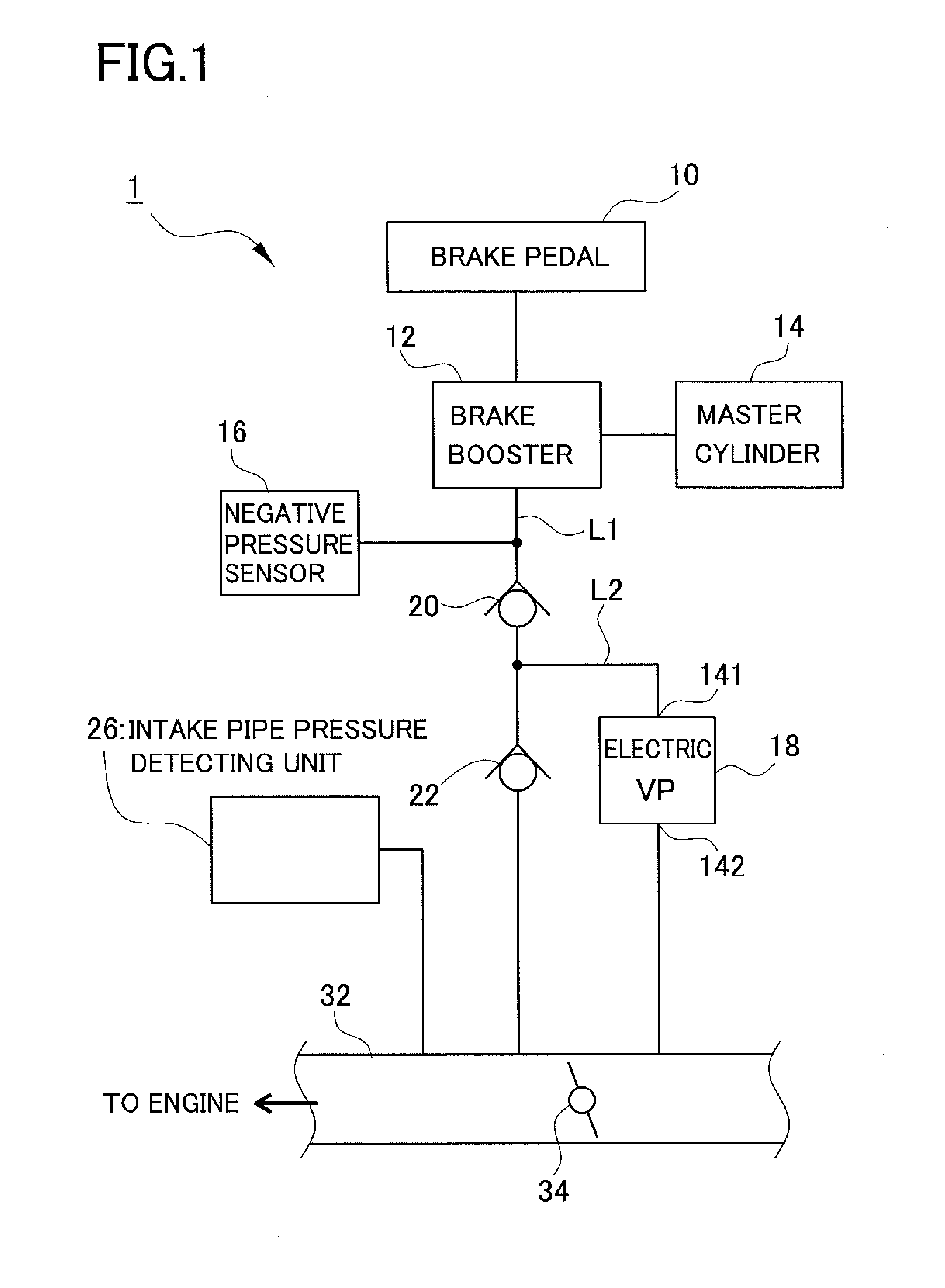
[0056]This brake system is first explained referring to FIGS. 1 and 2. FIG. 1 is a schematic configuration view of the brake system including the electric vacuum pump in the present embodiment. FIG. 2 is a block diagram showing a control system of the brake system including the electric vacuum pump in the present embodiment.

[0057]A brake system 1 in the present embodiment includes, as shown in FIGS. 1 and 2, a brake pedal 10, a brake booster 12, a master cylinder 14, a negative pressure sensor 16, an electric vacuum pump 18 (labeled “Electric VP” in the figure), a first check valve 20, a second check valve 22, an ECU 24, an intake pipe pressure detection unit 26, an engine stop determination unit 28, an...


PUM


Abstract

In an electric vacuum pump, a pump housing and a lower-end cover member respectively include positioning retainers respectively formed on outer peripheries of the pump housing and the lower-end cover member. A case includes positioning retainers each protruding inward from an inner peripheral surface of the case. The positioning retainers are in contact with the positioning protrusions, thereby positioning the pump housing and the lower-end cover member with respect to the case. The positioning protrusions are formed with screw holes.

Description

CROSS-REFERENCE TO RELATED APPLICATIONS[0001]This application is based upon and claims the benefit of priority from the prior Japanese Patent Applications No. 2013-040766 filed Mar. 1, 2013 and No. 2013-177796 filed Aug. 29, 2013, the entire contents of which are incorporated herein by reference.BACKGROUND OF THE INVENTION[0002]1. Field of the Invention[0003]The present invention relates to a vacuum pump for generating negative pressure to be used in a brake booster of a vehicle such as a car.[0004]2. Related Art[0005]A brake device for car is provided with a brake booster for amplifying a braking force by utilizing negative pressure in an intake pipe (“intake-pipe negative pressure”) of an engine. In recent years, pumping loss is reduced in response to demands for low-fuel consumption and thus the negative pressure in the intake pipe tends to decrease. Furthermore, for a hybrid vehicle, an electric vehicle, or a vehicle with an idling stop function, there is a case where the intake...

Claims


Application Information

Patent Timeline
IPC IPC(8): F04B35/04
CPCF04B35/04F04C25/02F04C29/04F04C29/06F04C18/3441F04C2240/30
Inventor SUGIMOTO, ATSUSHIMAKINO, KATSUHIKOYAMANAKA, SHOTA
Owner AISAN IND CO LTD
Why Eureka
Try Eureka