
Embolic protection device

a protection device and embolism technology, applied in the field of embolism prevention, can solve problems such as brain cell death and potential life-threatening complications

Active Publication Date: 2014-09-04
ST JUDE MEDICAL CARDILOGY DIV INC
View PDF5 Cites 20 Cited by
  • Summary
  • Abstract
  • Description
  • Claims
  • Application Information

AI Technical Summary

Benefits of technology

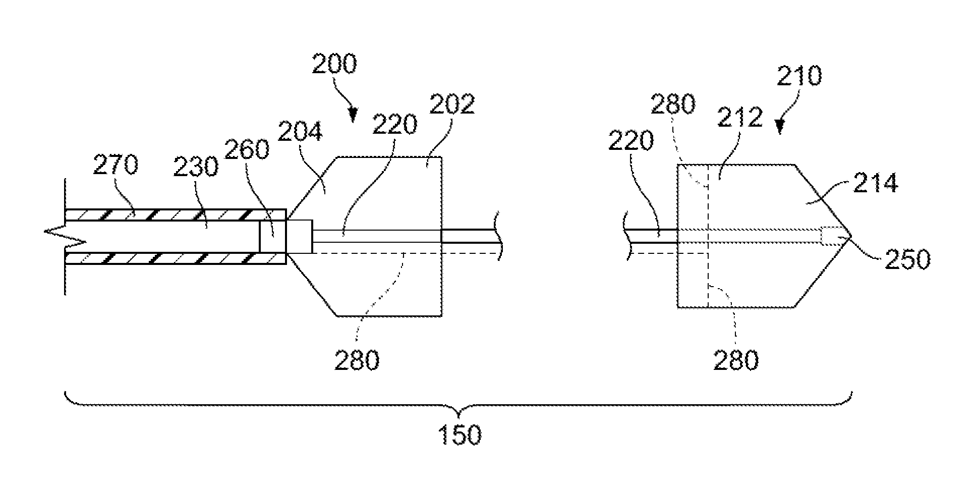
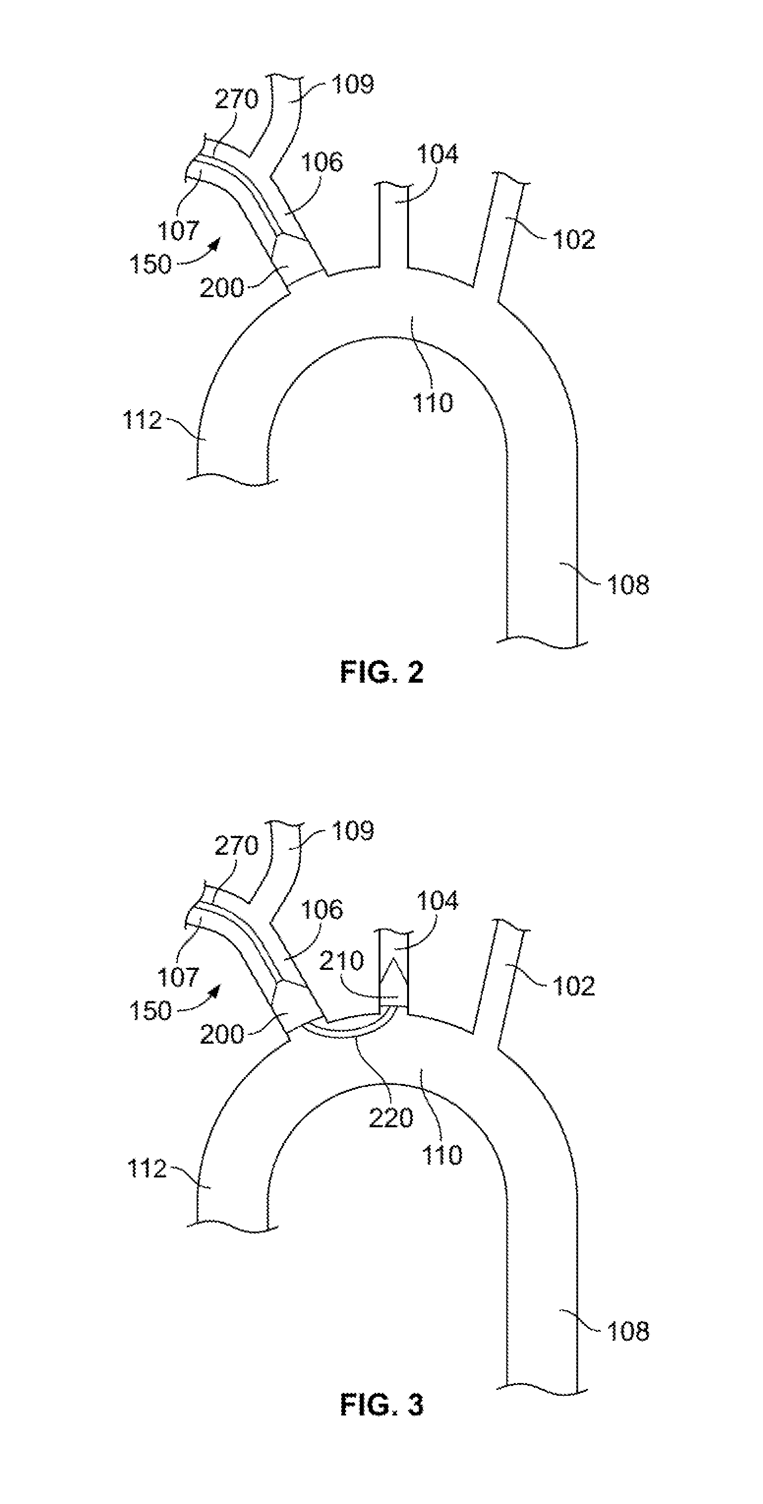
The present patent text describes an embolic protection device and method for use in patient procedures to prevent the formation of blood clots that can be potentially harmful to the patient. The device includes two filters, one connected to a tube and one connected to a wire. A first wire extends through the tube and into the filter, and a second wire extends through the wire and into the filter. The filters are designed to be placed in blood vessels to capture any embolic materials that may be released during the procedure and prevent them from causing harm to the patient. The device can be easily guided and positioned using a steerable guide wire and a tool for manipulating the wires. Overall, the device allows for safer and more effective procedures by reducing the risk of harmful embolic events.

Problems solved by technology

During a surgical intervention, such as a cardiac intervention, a vascular intervention, or a coronary intervention, tissue, plaque, and / or other masses may be dislodged due to the intervention, resulting in an embolus.
These emboli are capable of traveling far from their origins, migrating to other sites of the vasculature and resulting in potentially life threatening complications.
For example, an embolus may travel through the carotid artery and inhibit the flow of blood to the brain, which may result in the death of brain cells, i.e., cause a stroke.

Method used


Image

  • Embolic protection device
  • Embolic protection device
  • Embolic protection device

Examples


Embodiment Construction

[0021]A continuing need exists for devices and systems that inhibit emboli from traveling to parts of a patient's vasculature where they may block blood flow to critical organs and threaten the life of the patient.

[0022]Particular embodiments of the present disclosure are described with reference to the accompanying drawings. In the figures and in the description that follow, like reference numerals identify similar or identical elements. As shown in the drawings and as described throughout the following description, the term “proximal” refers to the end of the device that is closer to the user and the term “distal” refers to the end of the device that is farther from the user.

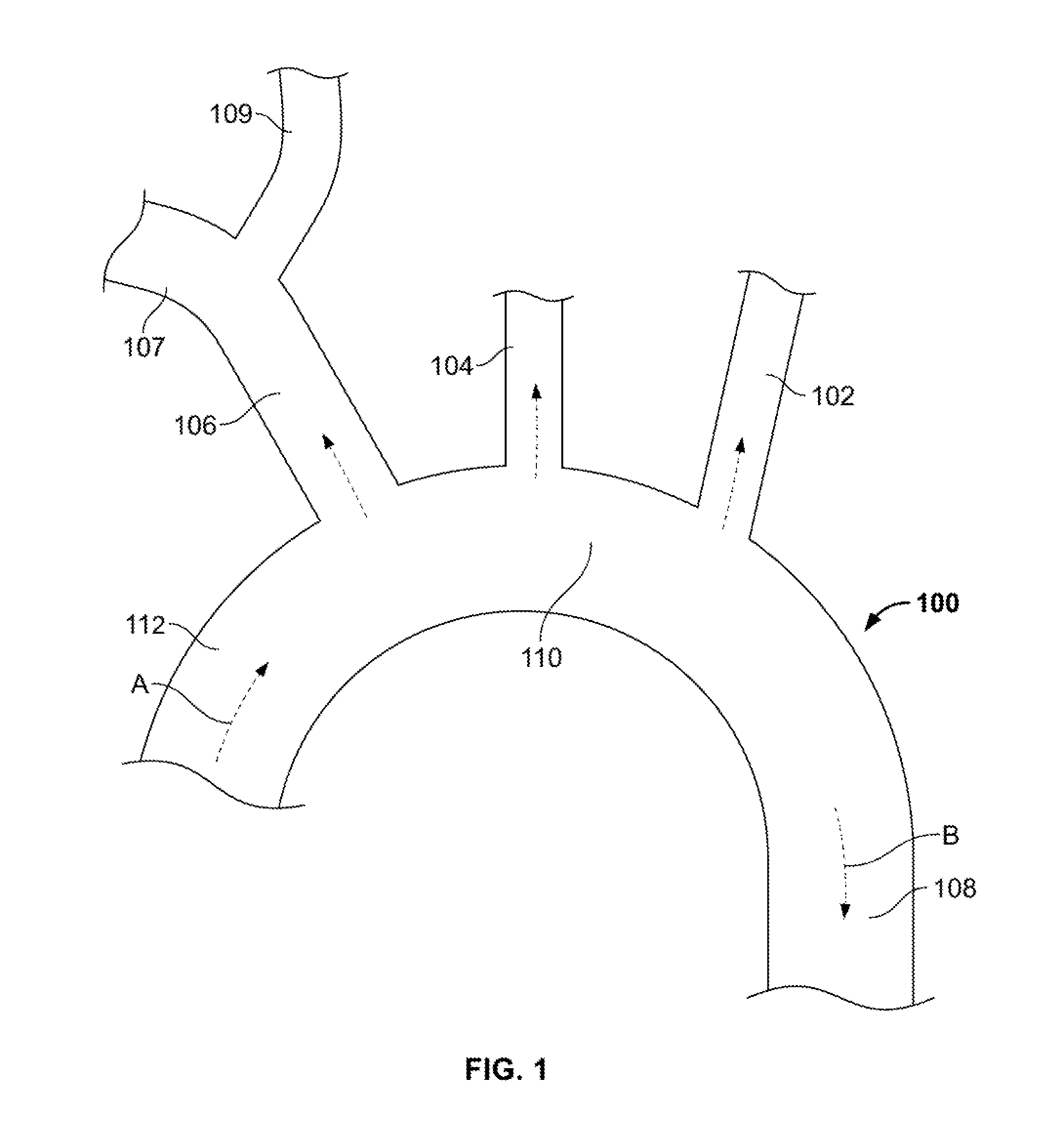
[0023]FIG. 1 illustrates aorta 100, the largest artery in the body, originating from the left ventricle (not shown) and extending down to the abdomen. Blood flows as indicated by arrow “A” from the left ventricle, through the aortic valve (not shown), through ascending aorta 112 to aortic arch 110. Three major...


PUM


Abstract

Embolic protection devices useful for filtering emboli during interventional cardiac, vascular, or other procedures are described. The device can include first and second expandable mesh filters having open and closed ends. The first filter is attached to a catheter at its closed end. The second filter is attached to a steerable guide wire at its closed end. The second filter includes a cinching wire circumferentially attached to the filter. The filters are deployed in separate vessels, such as the brachiocephalic artery and the left common carotid artery. A procedure is performed, and the filters trap any emboli travelling through the path of the filters. At the end of the procedure, the second filter is closed using the cinching wire, and retracted into the first filter. Both the first and second filters are collapsed into a sheath and removed from the body with along with any emboli trapped in the filters.

Description

BACKGROUND OF THE DISCLOSURE[0001]The present disclosure is related to protecting against embolism, and more particularly to devices, systems, and methods for the filtration and removal of debris within blood vessels.[0002]Arterial embolism is a sudden interruption of blood flow to an organ or body part due to an embolus, e.g., debris or a clot. During a surgical intervention, such as a cardiac intervention, a vascular intervention, or a coronary intervention, tissue, plaque, and / or other masses may be dislodged due to the intervention, resulting in an embolus. These emboli are capable of traveling far from their origins, migrating to other sites of the vasculature and resulting in potentially life threatening complications. For example, an embolus may travel through the carotid artery and inhibit the flow of blood to the brain, which may result in the death of brain cells, i.e., cause a stroke. A blockage of the carotid arteries is the most common cause of a stroke.BRIEF SUMMARY OF...

Claims


Application Information

Patent Timeline
Patent Type & Authority Applications(United States)
IPC IPC(8): A61F2/01
CPCA61F2/01A61F2002/016A61F2230/0067A61F2230/008A61F2250/0063A61F2/012
Inventor LAINE, ROBERT M.
Owner ST JUDE MEDICAL CARDILOGY DIV INC
Learn More