Fluid seal assembly

a technology of assembly and seal, which is applied in the direction of engine seals, metal-working devices, mechanical devices, etc., can solve the problems of assembly not improving the retention of the seal casing, requiring additional steps in the manufacturing process and extra parts, and not cost effective in mass production, so as to improve the retention in the metal bore, eliminate the spring back of the assembly, and improve the effect of manufacturing cos

Inactive Publication Date: 2014-09-11
AB SKF
View PDF17 Cites 2 Cited by
  • Summary
  • Abstract
  • Description
  • Claims
  • Application Information

AI Technical Summary

Benefits of technology

[0017]An advantage of the present invention is to provide an improved fluid seal assembly that eliminates problems associated with prior art designs such as static leakage of oil, clogging up the spirals with carbonized oil that negatively impact lifecycle of the fluid seals.
[0018]Another advantage of the present invention is to provide the fluid seal assembly that improves retention in metal bores during thermal expansion and eliminate spring back of the assembly after installation.
[0019]Still another advantage of the present invention is to provide the fluid seal assembly that is cost effective in manufacturing thereby allowing one shaft size compression or injection mold to make many different seals for the same shaft size, but many different bore sizes.
[0020]Still another advantage of the present invention is to provide the fluid seal assembly that replaces prior art designs of the fluid seals and provides an improved sealing solution that allows some resilience in order to improve retention of the seals in the bore during thermal cycles.
[0021]Other advantages and meritorious features of this invention will be more fully understood from the following description of the preferred embodiment, the appended claims, and the drawings; a brief description of which follows.

Problems solved by technology

The seal assembly taught by the U.S. Pat. No. 3,856,368 to Andersen presents a design that required multitude of parts to be engaged with one another thereby requiring additional steps in manufacturing process and extra part, which is not cost effective in mass production.
In addition, the design of this seal assembly does not improve retention of the seal casing inside the housing during thermal expansion and does not eliminate spring back effect of the seal assembly as the cylindrical member rotates relative the seal casing.
However, the design of the seal assembly taught by the U.S. Pat. No. 5,350,181 to Horve does not improve retention of the seal casing inside the housing during thermal expansion and does not eliminate spring back effect of the seal assembly as the cylindrical member rotates relative the seal casing.
Painted smooth surface of the coating provides 20% less frictional torque (drag) during installation resulting in power savings and a reduction of the possibility of early failure due to damage, and does not provide retention during thermal expansion.

Method used


Image

  • Fluid seal assembly
  • Fluid seal assembly
  • Fluid seal assembly

Examples


Embodiment Construction

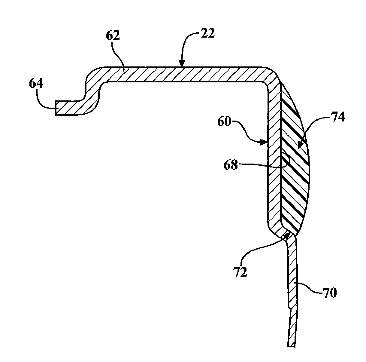
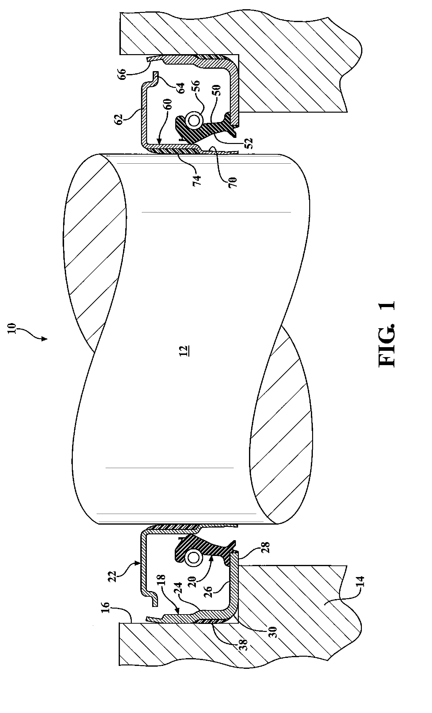
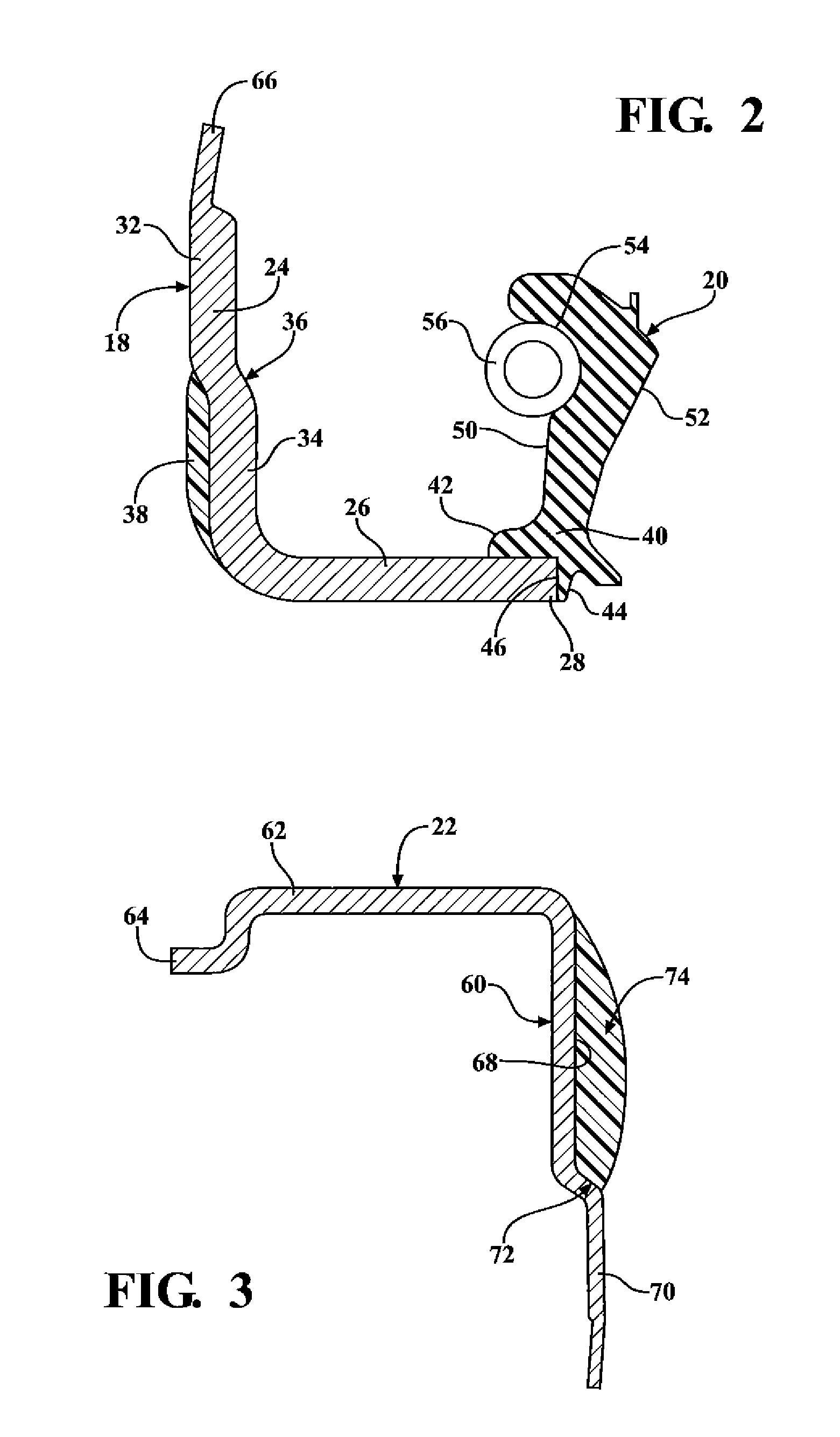
[0027]Referring to the Figure, wherein like numerals indicate like or corresponding parts throughout the several views, a fluid seal assembly (the assembly) of the present invention is generally shown at 10FIGS. 1 through 3. The assembly 10 has numerous applications including and not limited to sealing vehicular engine crankshafts, transmission shafts, bearing lubrication systems, compressor shaft support assemblies, and the like, without limiting the scope of the present invention.

[0028]FIG. 1, for example, illustrates an environment, wherein the assembly 10 is disposed between a counterpart, such as a shaft 12 and a housing, such as an engine wall 14 or a housing defining a counter bore 16. Those skilled in the mechanical art will appreciate that the shaft 12 and the engine wall 14 are shown for exemplary purposes only and are not intended to limit the scope of the present invention.

[0029]Referring back to FIGS. 1 and 2, a cross sectional view of the assembly 10 disposed between t...


PUM

PropertyMeasurementUnit
outer diameteraaaaaaaaaa
internal diameteraaaaaaaaaa
inner diameteraaaaaaaaaa

Abstract

A fluid seal assembly (the assembly) of the present invention is disposed between an outer surface, i.e. engine block or any other part that requires application of the assembly and a rotatable member, such as, for example a shaft, wherein the assembly circumscribes the shaft and lubricated the shaft and the same rotates around the axis. The assembly includes a primary seal and a wear sleeve. The primary seal includes a casing and a seal element that contacts a sealing surface on the wear sleeve. The casing includes an outer diameter and an outer seal molded onto the outer diameter. The wear sleeve has a cylindrical portion defining an inner diameter and an inner seal molded into the inner diameter of the wear sleeve. The outer and inner seals of the present invention provide improved retention in metal bores during thermal expansion and eliminate spring back effect of the assembly after installation.

Description

FIELD OF THE INVENTION[0001]The present invention relates generally to fluid seals for use with relatively rotatable members, such as shafts and the like.BACKGROUND OF THE INVENTION[0002]Fluid seals assemblies of various types are used in numerous applications including and not limited to sealing vehicular engine crankshafts, transmission shafts, bearing lubrication systems, compressor shaft support assemblies, and the like. These fluid seal assemblies are designed to retain and seal oil or grease in a predetermined location for lubricating the shaft and to prevent ingress of environmental contaminants. These fluid seal assemblies are also designed for the sealing of openings between rotating and stationary component or between two components in relative motion to form a barrier to retain lubricants or liquids, exclude contaminants, separate fluids, and confine pressure. It is important to constantly retain and seal oil or grease in a predetermined location for lubrication of the sh...

Claims


Application Information

Patent Timeline
Patent Type & Authority Applications(United States)
IPC IPC(8): F16J15/32
CPCF16J15/3276F16J15/3264Y10T29/49297
Inventor WADE, ALFRED ROBERTTIPPS, JOHN RANDOLPHDANA, BRET THOMAS
Owner AB SKF
Why Eureka
Try Eureka