Method and apparatus for pipe pressure measurements

Inactive Publication Date: 2014-09-11
GE HITACHI NUCLEAR ENERGY AMERICAS
View PDF6 Cites 7 Cited by
  • Summary
  • Abstract
  • Description
  • Claims
  • Application Information

AI Technical Summary

Benefits of technology

[0010]Some example embodiments provide a method and/or apparatus for pipe pressure measurements using a strain gauge collar that reduces the installation and exposure time for operators of a nuclear

Problems solved by technology

Conventional BWRs can experience damage resulting from aero-acoustic loading of the steam dryer during operation.
Some conventional BWRs have experienced significant degradation of the steam dryer after operating at power levels in excess of the original licensed thermal power.
For example, the aero-acoustic loading of the steam dryer can result in vibration of the stea

Method used


Image

  • Method and apparatus for pipe pressure measurements
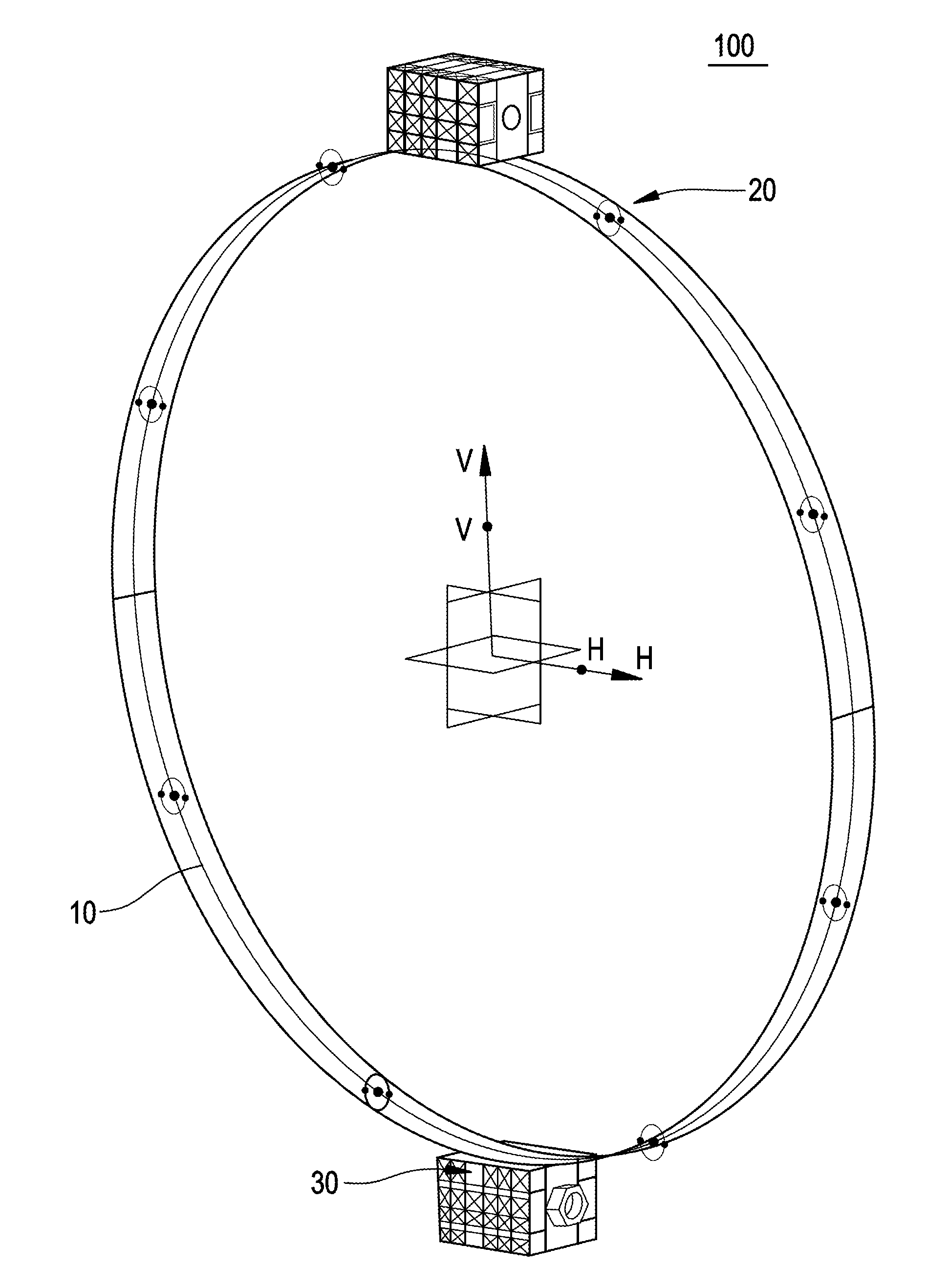
  • Method and apparatus for pipe pressure measurements
  • Method and apparatus for pipe pressure measurements

Examples


Embodiment Construction

[0018]Detailed example embodiments are disclosed herein. However, specific structural and functional details disclosed herein are merely representative for purposes of describing example embodiments. Example embodiments may, however, be embodied in many alternate forms and should not be construed as limited to only the embodiments set forth herein.

[0019]Accordingly, while example embodiments are capable of various modifications and alternative forms, embodiments thereof are shown by way of example in the drawings and will herein be described in detail. It should be understood, however, that there is no intent to limit example embodiments to the particular forms disclosed, but to the contrary, example embodiments are to cover all modifications, equivalents, and alternatives falling within the scope of example embodiments. Like numbers refer to like elements throughout the description of the figures.

[0020]It will be understood that, although the terms first, second, etc. may be used h...


PUM

PropertyMeasurementUnit
Angleaaaaaaaaaa
Electrical resistanceaaaaaaaaaa

Abstract

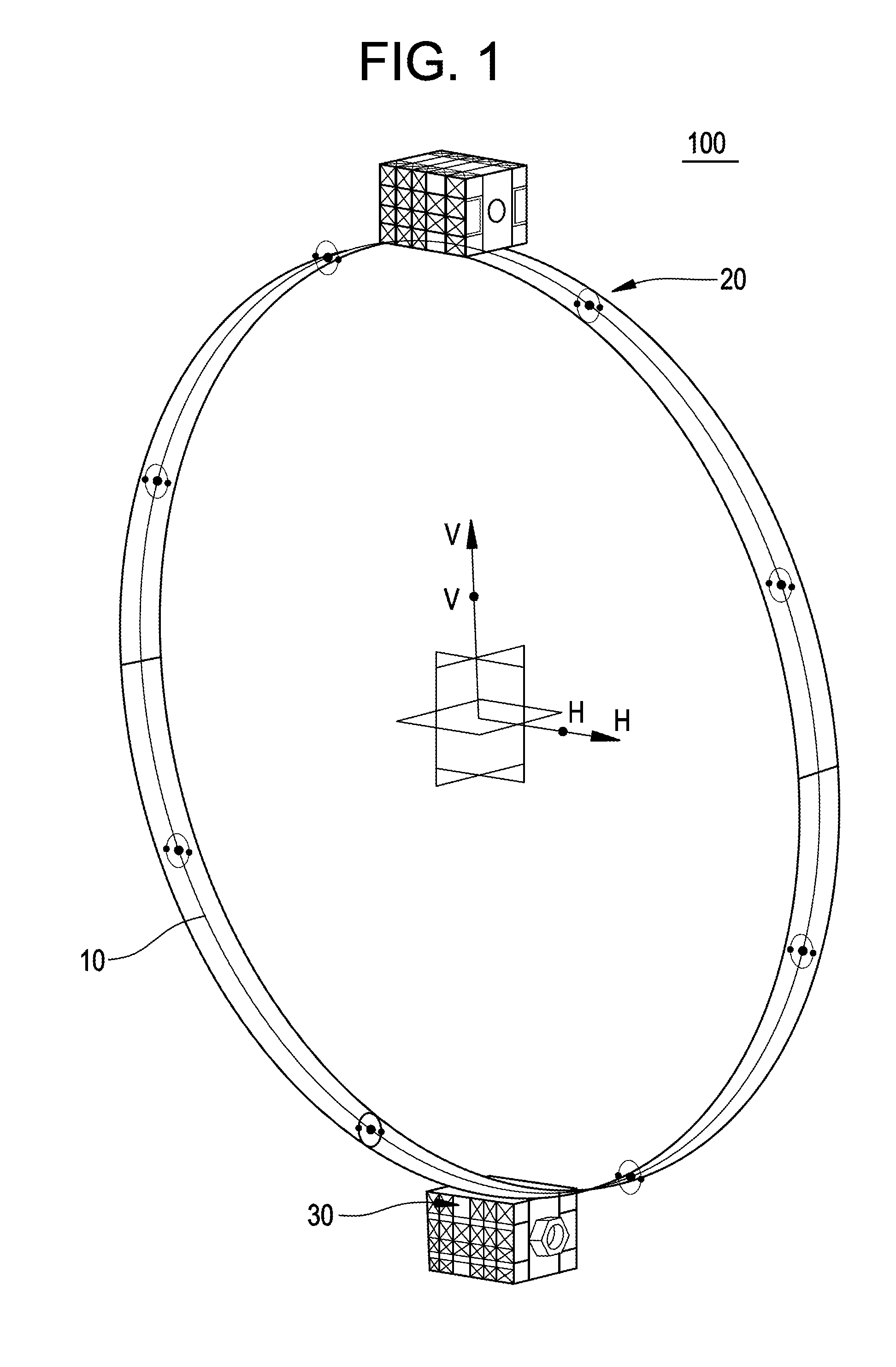
A strain gauge collar includes at least one strain gauge installed on a base and at least one clamp on the base. The at least one clamp is configured to attach the strain gauge collar to a main steam line (MSL) as a single unit.

Description

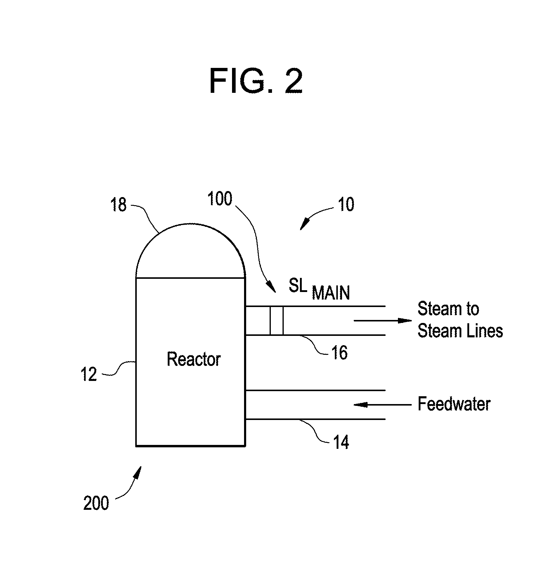
BACKGROUND[0001]1. Field[0002]Some example embodiments relate generally to a method and / or apparatus for pipe pressure measurements, and more particularly to a method and / or apparatus for pipe pressure measurements that reduce installation and exposure time for the operators of a nuclear facility.[0003]2. Related Art[0004]A reactor pressure vessel (RPV) of a nuclear reactor such as a boiling water reactor (BWR) typically has a generally cylindrical shape and is closed at both ends, e.g., by a bottom head and a removable top head. A top guide typically is spaced above a core plate within the RPV. A core shroud, or shroud, typically surrounds the reactor core and is supported by a shroud support structure. The shroud has a generally cylindrical shape and surrounds both the core plate and the top guide. There is a space or annulus located between the cylindrical reactor pressure vessel and the cylindrically-shaped shroud.[0005]Heat is generated within the core and water circulated up t...

Claims


Application Information

Patent Timeline
IPC IPC(8): G01L9/04
CPCG01L9/04G01L1/2231G01L9/0027G21C17/00G21C17/10Y02E30/30Y10T29/49959
Inventor OFFER, HENRY P.EWIDA, KHALED M.SCHROEDER, GLENNNEIHEISEL, MIKEHADJIT, RABAHSCHNACKENBERG, JOEL C.
Owner GE HITACHI NUCLEAR ENERGY AMERICAS
Why Eureka
Try Eureka