Method and devices for centralizing a casing

a casing and casing technology, applied in the direction of drilling casings, wellbore/well accessories, pipes, etc., can solve the problems of increasing resistance and potential snagging, reducing the mechanical integrity of the collar substantially, and reducing the friction of the casing. , to achieve the effect of reducing the friction of the casing

Inactive Publication Date: 2014-09-11
PORTABLE COMPOSITE STRUCTURES
View PDF1 Cites 11 Cited by
  • Summary
  • Abstract
  • Description
  • Claims
  • Application Information

AI Technical Summary

Benefits of technology

[0038]FIG. 13 is a perspective cut-away view of a wellbore illustrating three arcuate centralizers after being deployed wherein the centralizers include roller bearings to reduce friction of a casing as it is deployed; and

Problems solved by technology

With the advent of deeper wells and horizontal drilling, centralizing the casing has become more important and more difficult to accomplish.
Unfortunately, these centralizers increase the profile of the casing, thereby causing increased resistance and potential snagging during casing installation.
The challenge in developing an effective deployable centralizer is to make it as low profile as possible, actuate deployment upon demand, and to overcome de-centralizing force.
The recess substantially decreases the mechanical integrity of the collar due to the removal of a large portion of the collar wall to accommodate the bow-springs.
The collars of the casing centralizer disclosed in this patent also require several additional manufacturing steps, including the formation of both internal and external (alternating) upsets in each collar to form the aligned openings for receiving and securing bow-springs, a time-consuming process that further decreases the mechanical integrity of the collar.

Method used


Image

  • Method and devices for centralizing a casing
  • Method and devices for centralizing a casing
  • Method and devices for centralizing a casing

Examples


Embodiment Construction

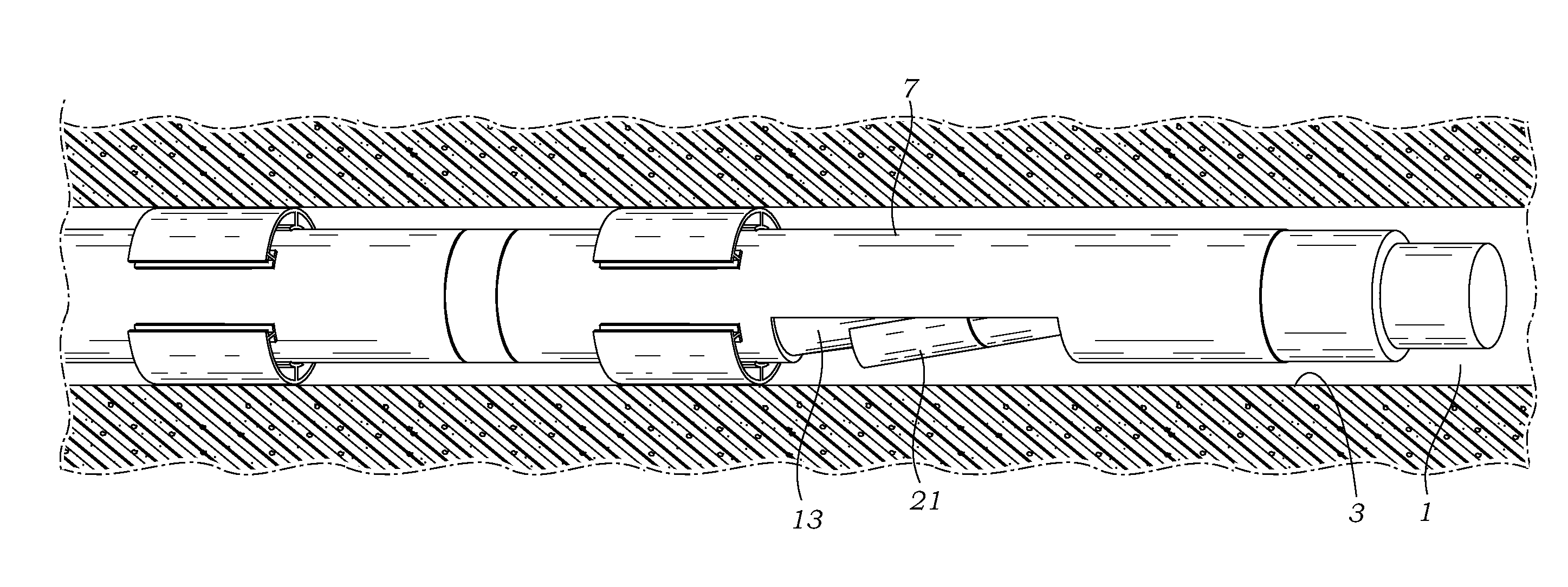
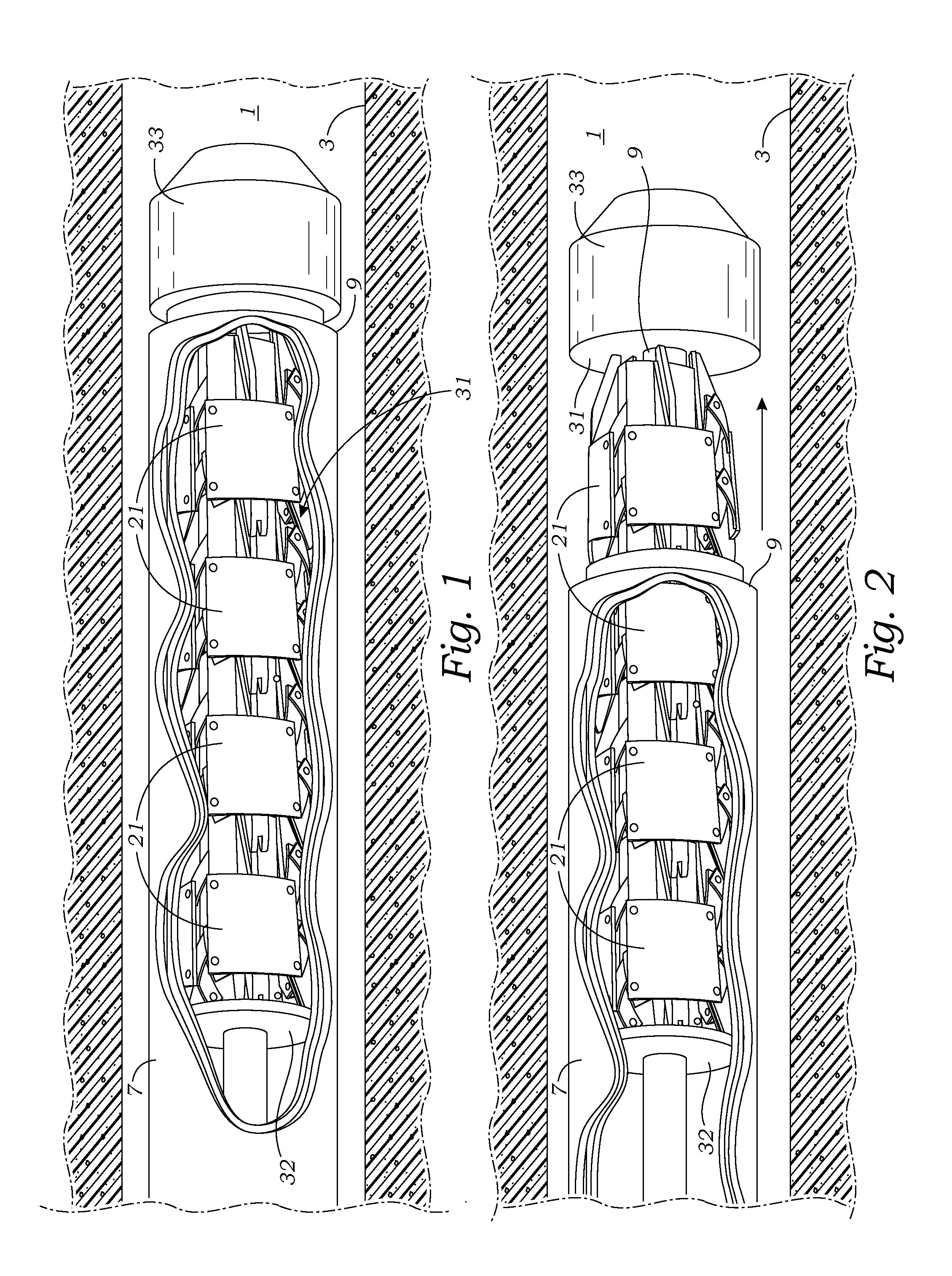
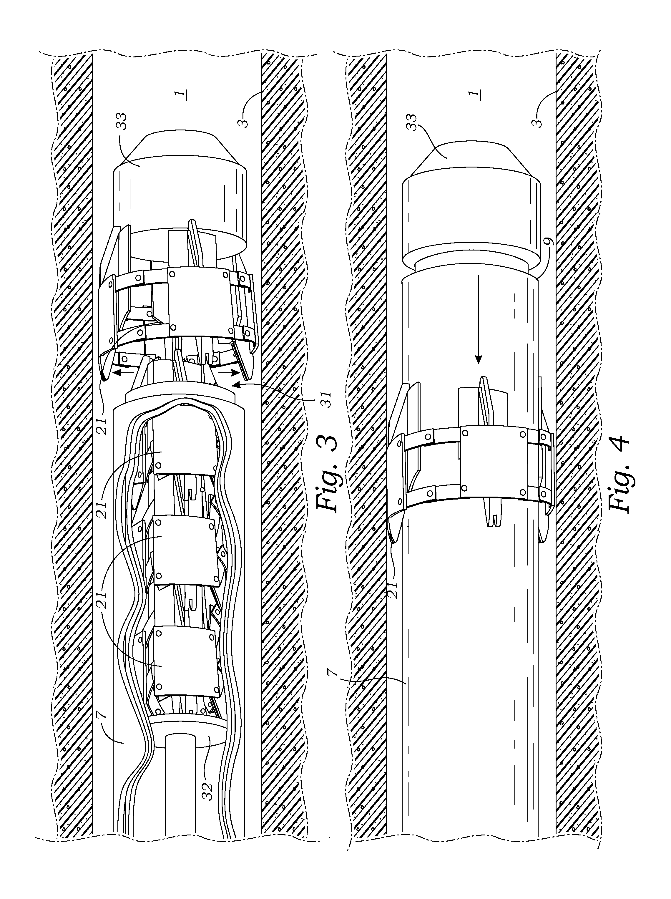
[0040]With reference to all FIGS. 1-14, the present invention is directed to various apparatus and methods for installing a centralizer 21 wherein the centralizer 21 has been transported to its position within the wellbore 1, but not attached to a casing's exterior. Instead, the centralizer 21 is transported to its desired location within the wellbore from within a pipe's interior and then ejected from the pipe 7. The deployment of the centralizer 21 from the pipe can be determined by various methods known to those skilled in the art, such as by employing a plunger 32 which simply pushes the centralizer from the pipe's distal end 9. However, the ejection of the centralizer 21 can also be effected through a portal 13 formed into the pipe's sidewall, as illustrated in FIGS. 7-12. Preferably, the pipe is the casing used to extract a liquid or gas. However, an initial pipe may be dropped downhole to deploy the centralizers, and then retracted to allow the introduction of the well casing...


PUM


Abstract

New apparatus and methods are provided for positioning and attaching centralizers to the inside sidewalls of a wellbore. One or more centralizers are maintained in the interior of a pipe that is transported downhole into a well for deployment. Preferrably, the pipe is also the wellbore's casing and the centralizers are deposited in a top-down manner as the casing travels downhole. The centralizers of the present invention are constructed to have an at least partially circular structure with a central hole. The preferred centralizer has an expanding circular structure wherein the diameter of the centralizer is substantially uniform so as to form an annular construction. Once deployed, the annular centralizer expands to engage the wellbore sidewall with the central hole expanded for passage of the well casing.

Description

RELATED APPLICATIONS[0001]The present application is a continuation-in-part of co-pending U.S. Provisional Patent Application Ser. No. 61 / 775,933 filed on Mar. 11, 2013.BACKGROUND OF THE INVENTION[0002]The present invention relates to the construction of subterranean wells. More particularly, the present invention relates to methods and constructions for centering a casing within a well, particularly an oil or gas well.[0003]A well is any boring through the Earth's surface that is designed to find and acquire liquids or gases. Wells for acquiring oil are termed “oil wells”. A well that is designed to produce mainly gas is called a “gas well”. Typically, wells are created by drilling a bore, typically 5 inches to 40 inches (12 cm to 1 meter) in diameter, into the earth with a drilling rig that rotates a drill string with an attached bit. After the hole is drilled, sections of steel pipe, commonly referred to as a “casing” and which are slightly smaller in diameter than the borehole, ...

Claims


Application Information

Patent Timeline
Patent Type & Authority Applications(United States)
IPC IPC(8): E21B19/24
CPCE21B19/24E21B7/20E21B17/1014E21B17/1078
Inventor JEWETT, SCOTT E.
Owner PORTABLE COMPOSITE STRUCTURES
Why Eureka
Try Eureka