Light Fixture

a technology for light fixtures and components, applied in the field of light fixtures, can solve the problems of difficult to achieve improved charachteristics and excellent heat dissipation of light fixture components, and achieve the effect of facilitating any needed servicing

Active Publication Date: 2014-09-11
IDEAL IND LIGHTING LLC
View PDF11 Cites 3 Cited by
  • Summary
  • Abstract
  • Description
  • Claims
  • Application Information

AI Technical Summary

Benefits of technology

[0025]The low-profile LED light fixture of this invention may be a surface-mount fixture for mounting on a surface of a structure such that, when the fixture is installed, the back surface of the base plate is substantially against the structure surface—with no portion of the light f...

Problems solved by technology

LED light fixtures present particularly challenging problems which relate to size and configuration, ease of installation, servicing and configurational...

Method used


Image

  • Light Fixture
  • Light Fixture
  • Light Fixture

Examples


Embodiment Construction

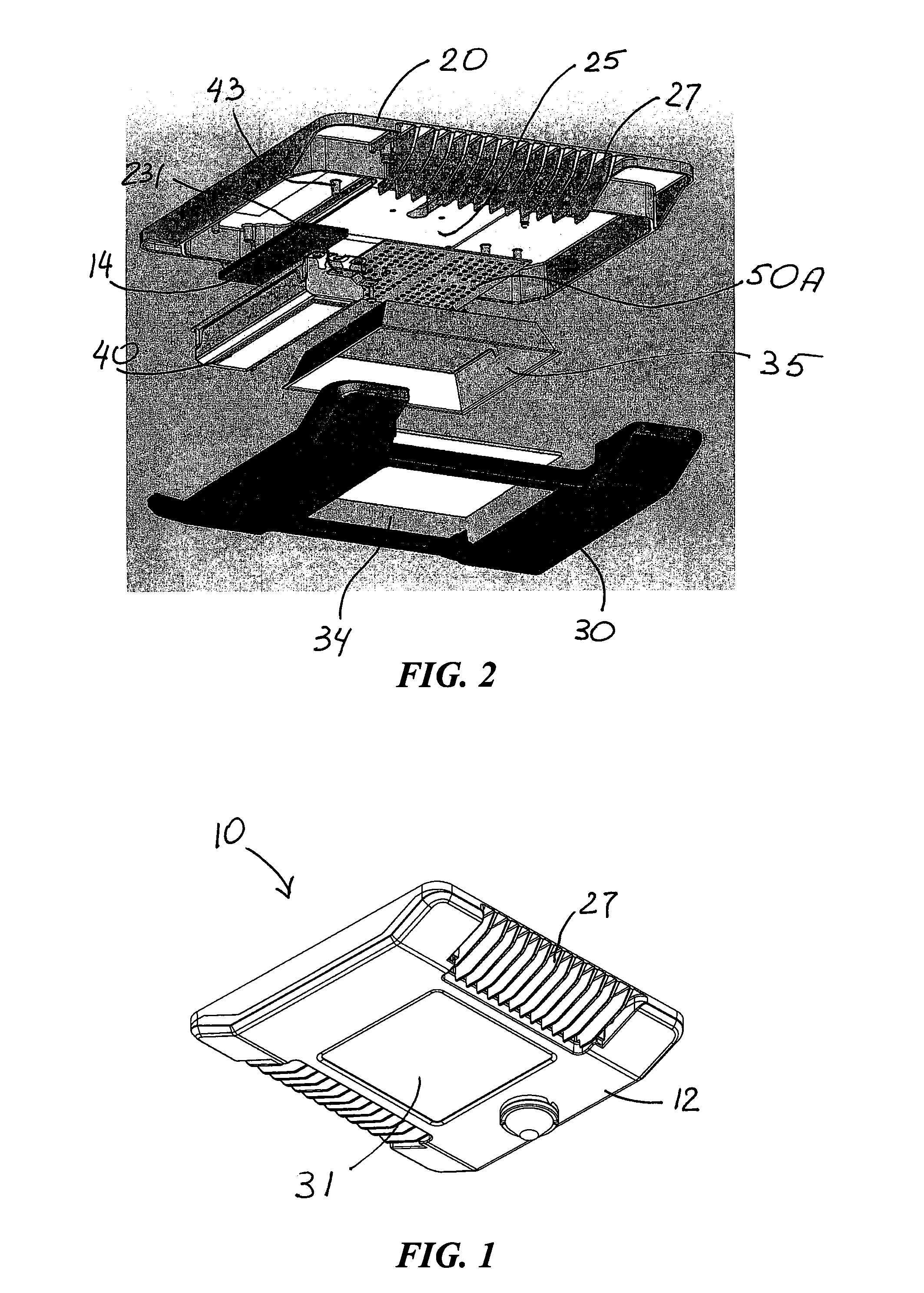
[0045]FIGS. 1-25 illustrate exemplary embodiments of LED light fixtures in accordance with this invention. Common or similar parts in different embodiments are given the same numbers in the drawings; the light fixtures themselves are often referred to by the numeral 10.

[0046]As seen in FIGS. 1, 2 and 6, light fixture 10 includes a housing 12 defining an enclosure 11 formed by a base 20 and a cover 30 movably secured with respect to base 20. FIGS. 3-7 show a power-circuitry unit 40 secured with respect to base 20 such that, when the cover 30 is closed, power-circuitry unit 40 is in thermal communication with cover 30.

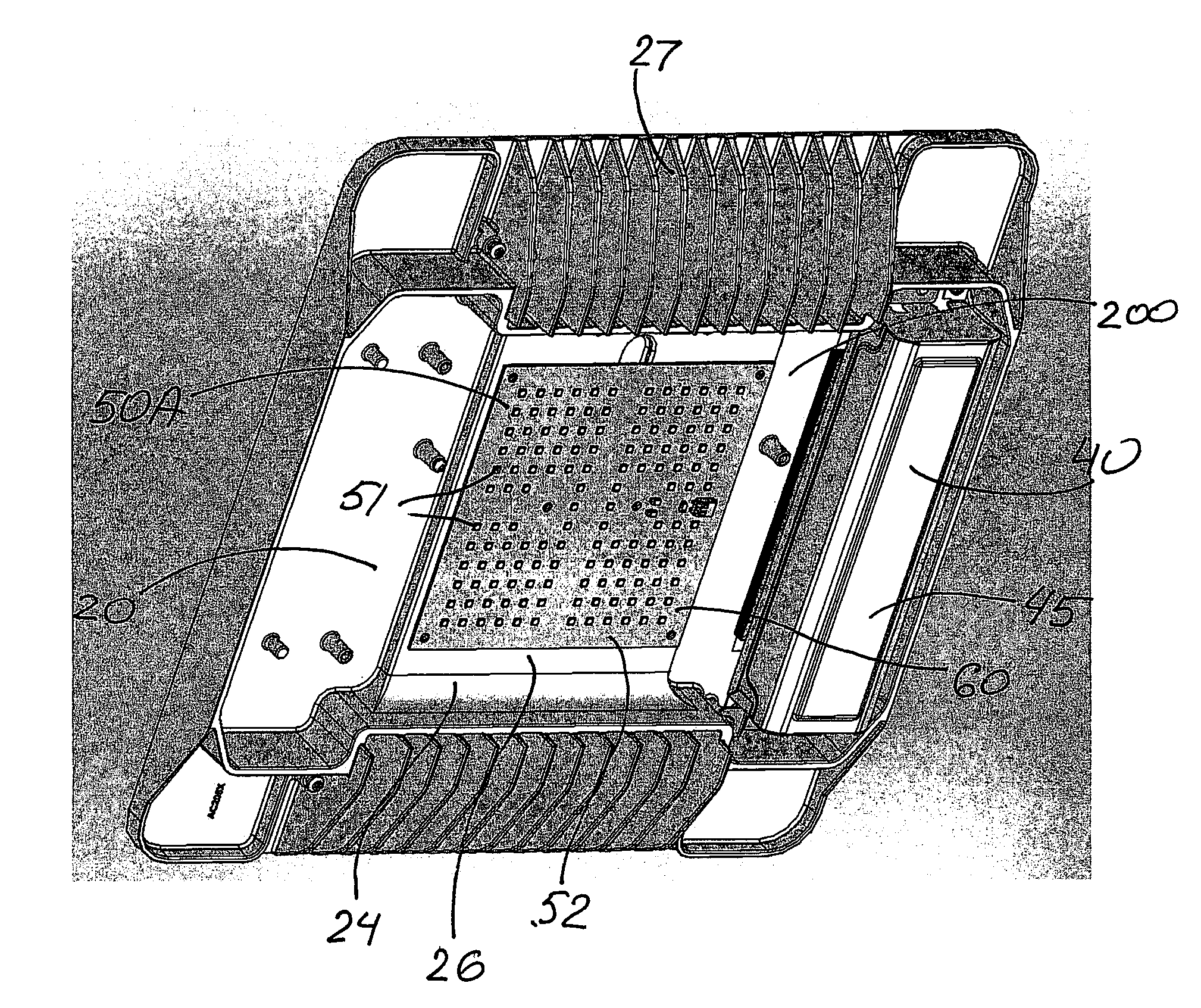
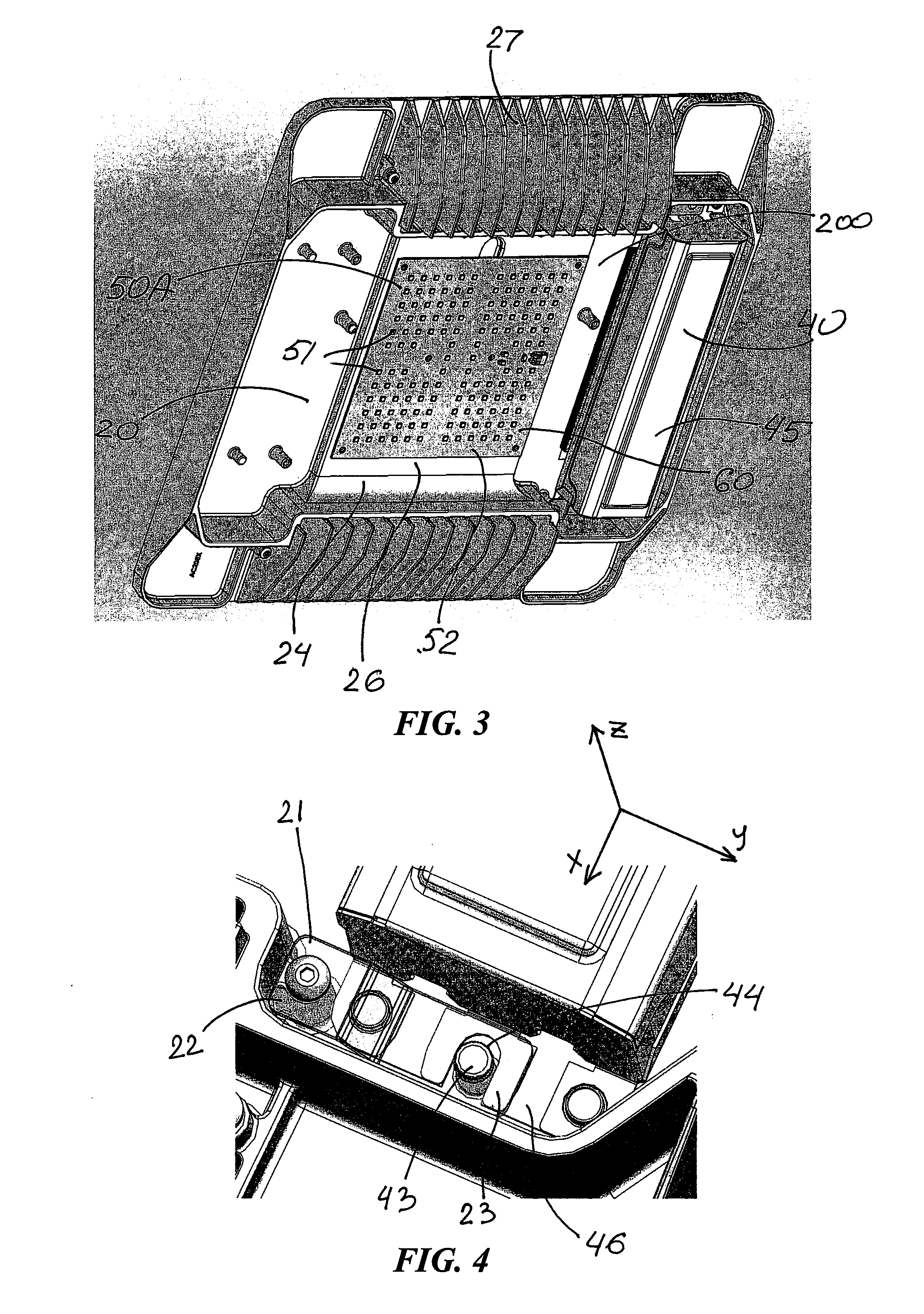
[0047]As best illustrated in FIGS. 2, 3 and 5, a light emitter is secured with respect to housing 12 within enclosure 11. FIGS. 3 and 5 show two alternative light emitters 50A and 50B, each of which includes LED sources 51 on an LED-circuit board 52 which is secured with respect to base 20. As seen in FIGS. 3, 5 and 15-17, which illustrate alternative embodiments, the li...


PUM


Abstract

An LED light fixture including a heat-sink body having a circuit-board mounting surface and an aperture member supported over the circuit-board mounting surface and forming an optical aperture. An LED circuit board is affixed in thermal-contact relationship to the circuit-board mounting surface in position between the mounting surface and the aperture member, the circuit board having an LED-populated area and a surrounding non-LED-populated area which extends beyond the optical aperture. In some other embodiments, the fixture is a low-profile LED light fixture including a cover and a base plate which has a substantially planar back surface, a front surface and heat-dissipating surfaces extending forward from the front surface. An LED circuit board and at least one LED power-circuitry unit, which are secured with respect to the front surface along side the heat-dissipating surfaces, do not extend behind the back surface of the base plate. The aspect ratio of the cross-section of the fixture orthogonal to the base plate between the back surface of the base plate and a forwardmost surface of the cover is greater than about 6.

Description

FIELD OF THE INVENTION[0001]This invention relates to light fixtures and, more particularly, to LED light fixtures.BACKGROUND OF THE INVENTION[0002]In recent years, the use of light-emitting diodes (LEDs) in development of light fixtures for various common lighting purposes has increased, and this trend has accelerated as advances have been made in the field. Indeed, lighting applications which previously had typically been served by fixtures using what are known as high-intensity discharge (HID) lamps are now being served by LED light fixtures. Such lighting applications include, among a good many others, so-called canopy lights for gasoline stations and the like, soffit-mounted light fixtures, surface-mounted light fixtures, and a variety of factory lighting and commercial building lighting.[0003]LED light fixtures present particularly challenging problems which relate to size and configuration, ease of installation, servicing and configurational efficiency. Achieving improvements...

Claims


Application Information

Patent Timeline
IPC IPC(8): F21V29/00
CPCF21V29/004F21V29/506F21V29/70F21V29/763F21K9/20F21Y2105/10F21Y2115/10F21V3/08F21V29/508F21V29/76Y02B20/30
Inventor KINNUNE, BRIAN L.GOELZ, DAVID P.LAY, JAMES MICHAELMILETICH, DON
Owner IDEAL IND LIGHTING LLC
Why Eureka
Try Eureka