Transverse-electromagnetic (TEM) radio-frequency coil for magnetic resonance

Active Publication Date: 2014-09-11
KONINKLJIJKE PHILIPS NV
View PDF9 Cites 5 Cited by
  • Summary
  • Abstract
  • Description
  • Claims
  • Application Information

AI Technical Summary

Benefits of technology

[0019]Although conventional TEM coils typically have a larger sensitivity profile in the z-direction, which can lead to safety issues with the specific absorption rate (SAR) of RF energy by patients (particularly in the head region) and can also reduce image quality due to additional sensitivity to noise pickup, the inventive concept is able to overcome these issues. The proposed concept provides L-shaped or U-shaped TEM-type coil elements having truncated or reduced sensitivity profiles in the z-direction which resolves the problems mentioned and yet still preserves the characteristics of the TEM coil having a well-defined RF ground (i.e. via an RF shield or screen). The lateral extensions of the U-shaped TEM coil elements h

Problems solved by technology

As birdcage coils float with respect to RF ground, the supply or feed of RF power in QBC-based MR systems is problematic, however, due to hot RF connections.
Further, this problem does not provide reliable basis for EM simulation of suc

Method used


Image

  • Transverse-electromagnetic (TEM) radio-frequency coil for magnetic resonance
  • Transverse-electromagnetic (TEM) radio-frequency coil for magnetic resonance
  • Transverse-electromagnetic (TEM) radio-frequency coil for magnetic resonance

Examples


Embodiment Construction

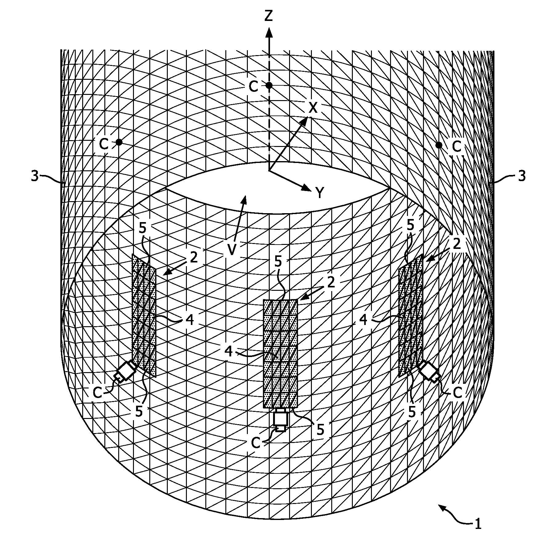
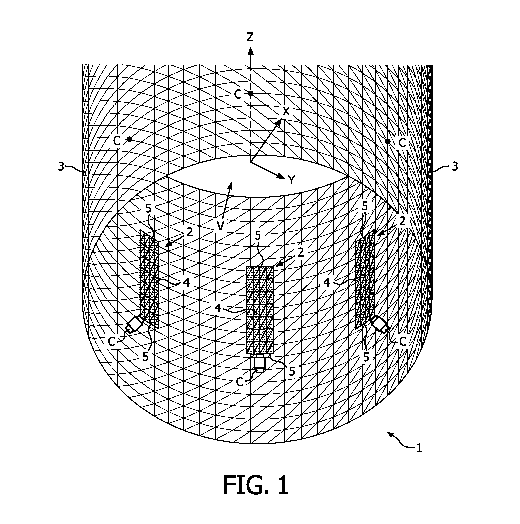
[0028]FIG. 1 shows a conventional transverse-electromagnetic (TEM) radio-frequency (RF) coil 1C for a magnetic resonance system, such as an MRI system. The conventional TEM coil 1C comprises a plurality of TEM coil elements 2 arranged within and encompassed by an RF shield 3 in the form of a cylindrical screen which functions as an RF ground for the coil 1C. A central axis of the cylindrical RF screen 3 corresponds to the z-axis of the coil 1C, as denoted by the Cartesian coordinates shown in FIG. 1. Each of the plurality of TEM coil elements 2 comprises an elongate coil strip section 4, and the TEM coil elements 2 are arranged such that the strip sections 4 are essentially parallel and spaced apart from one another at regular intervals around the z-axis inside the RF screen 3. Because the RF screen 3 in this example is circularly cylindrical, all of the strip sections 4 of the TEM coil elements 2 have basically the same radial spacing from the z-axis of the coil 1C. In this embodim...


PUM


Abstract

The present invention provides a transverse-electromagnetic (TEM) radio-frequency coil (1) for a magnetic resonance system, especially for a magnetic resonance imaging system. In particular, the inventive concept provides a coil (1) in which at least one of the opposite end regions of the elongate strip section (4) of each TEM coil element (2) has a lateral extension (6) transverse to a longitudinal extent of the strip section (4). These lateral extensions (6) combine with strip sections (4) to form L-or U-shaped TEM coil elements (2) and provide ‘ring-like’ current contributions resulting in a reduction of the z-sensitivity compared with a conventional TEM coil. The result is a coil array having TEM coil elements (2) that provide smaller sensitivity profiles in the z-direction, yet preserve the characteristics of a well-defined RF ground, e.g. via an RF shield or screen (3). The reduced field of view in z-direction not only reduces noise reception but also reduces the SAR generated in those regions during transmission.

Description

FIELD OF THE INVENTION[0001]The present invention relates to the field of magnetic resonance (MR), and more particularly to transverse-electromagnetic (TEM) radio-frequency (RF) coils for use in MR applications, as well as to a magnetic resonance (MR) system incorporating such coils.BACKGROUND OF THE INVENTION[0002]MR systems, and particularly magnetic resonance imaging (MRI) systems, frequently employ quadrature birdcage coils (QBCs), which have the advantage of a shorter field of view (FOV) in the z-direction (i.e. in the axial direction) while providing a higher signal-to-noise ratio (SNR) and also having lower total RF power requirements compared to TEM coils. As birdcage coils float with respect to RF ground, the supply or feed of RF power in QBC-based MR systems is problematic, however, due to hot RF connections. Further, this problem does not provide reliable basis for EM simulation of such a device. Particularly with degenerate birdcage coils, the RF cable connections are di...

Claims


Application Information

Patent Timeline
IPC IPC(8): G01R33/34
CPCG01R33/34092G01R33/34046G01R33/3453G01R33/3456
Inventor LEUSSLER, CHRISTOPHWIRTZ, DANIEL
Owner KONINKLJIJKE PHILIPS NV
Why Eureka
Try Eureka