
Method and apparatus for feeding electrical current into an electrical power supply system

a technology of electrical power supply system and electrical current, applied in mechanical apparatus, conversion with intermediate conversion to dc, machines/engines, etc., can solve the problems of rapid and accurate detection, asymmetries raise some problems, and the nature and fashion of such a contribution of synchronous generators cannot be basically influenced

Active Publication Date: 2014-09-11
WOBBEN PROPERTIES GMBH
View PDF14 Cites 10 Cited by
  • Summary
  • Abstract
  • Description
  • Claims
  • Application Information

AI Technical Summary

Benefits of technology

The patent describes a method for calculating the target currents of a three-phase network by taking into account the asymmetries of the network. By using a discrete Fourier transformation to determine the phase angle of the voltage, the method can adapt to non-ideal conditions in the network and provide a symmetrical current feed. The method can also predetermine the active and reactive power components of the target current by using the positive and negative sequence components of the voltage. This allows for efficient and effective control of the network.

Problems solved by technology

The nature and fashion of such a contribution from the synchronous generator however cannot basically be influenced because of the rigid coupling to the network.
In that respect taking account of network asymmetries raises some problems.
Firstly problems are involved in rapidly and accurately detecting network asymmetries.
In addition in the case of detection of asymmetries, the problem arises of targetedly compensating for same, which is not possible or is only limitedly possible with a strongly coupled synchronous generator.
The same problems occur in systems which do not use a synchronous generator but simulate same in terms of behavior.

Method used


Image

  • Method and apparatus for feeding electrical current into an electrical power supply system
  • Method and apparatus for feeding electrical current into an electrical power supply system
  • Method and apparatus for feeding electrical current into an electrical power supply system

Examples


Embodiment Construction

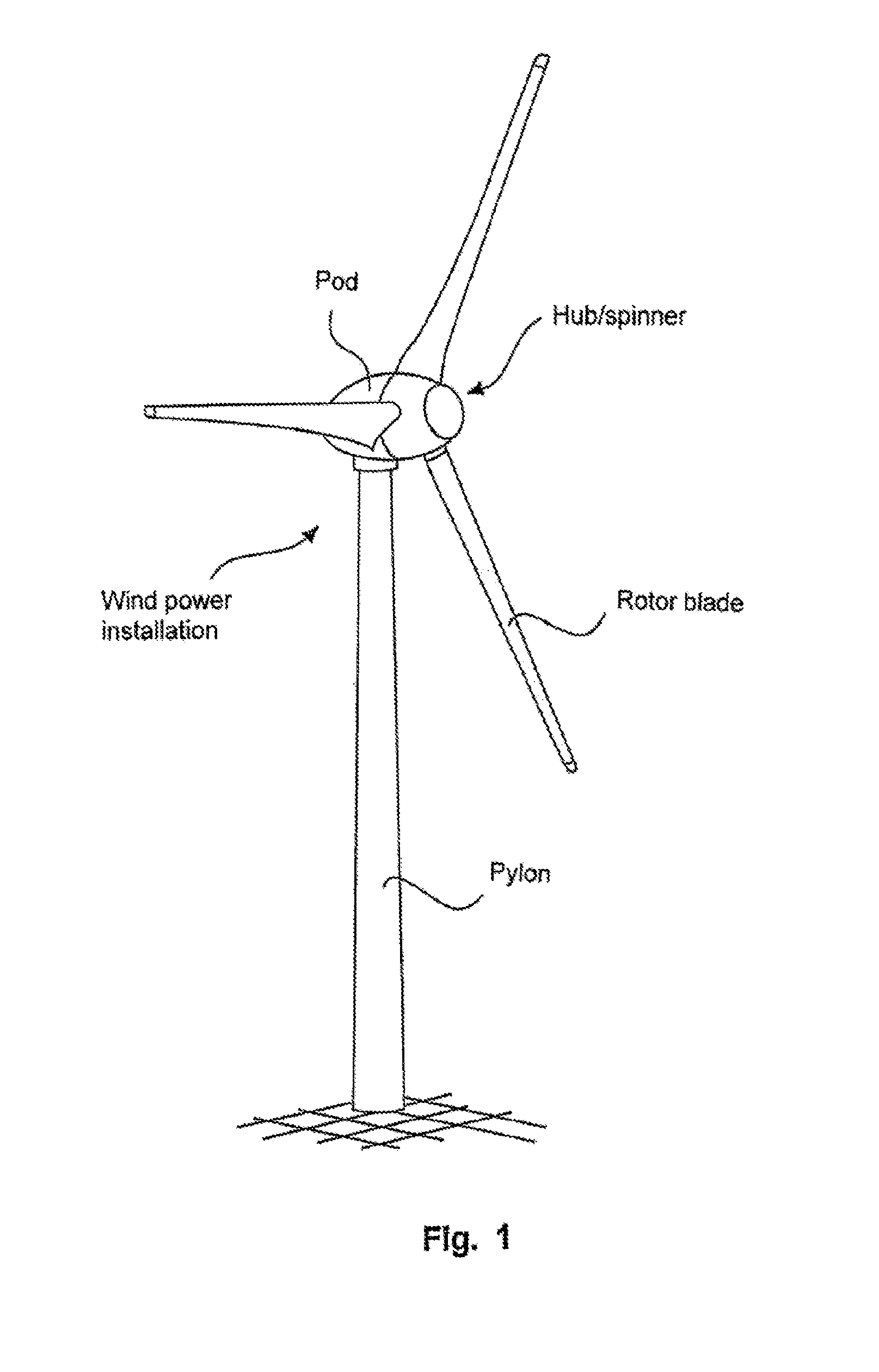
[0055]FIG. 1 shows a wind power installation which inter alia implements a method according to one embodiment of the invention and for that purpose has at least one frequency converter with appropriate actuation in order thereby to feed into an electric three-phase network.

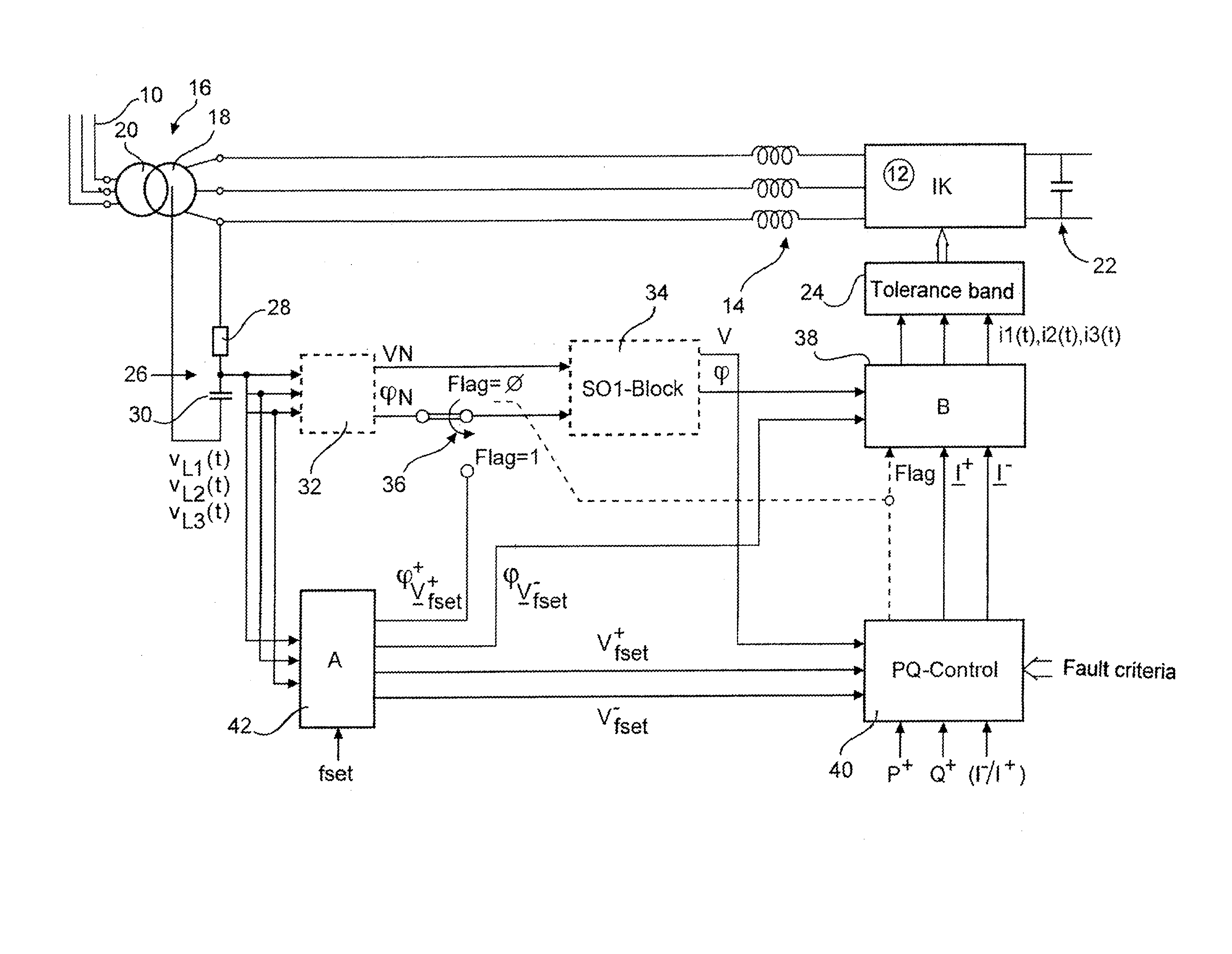
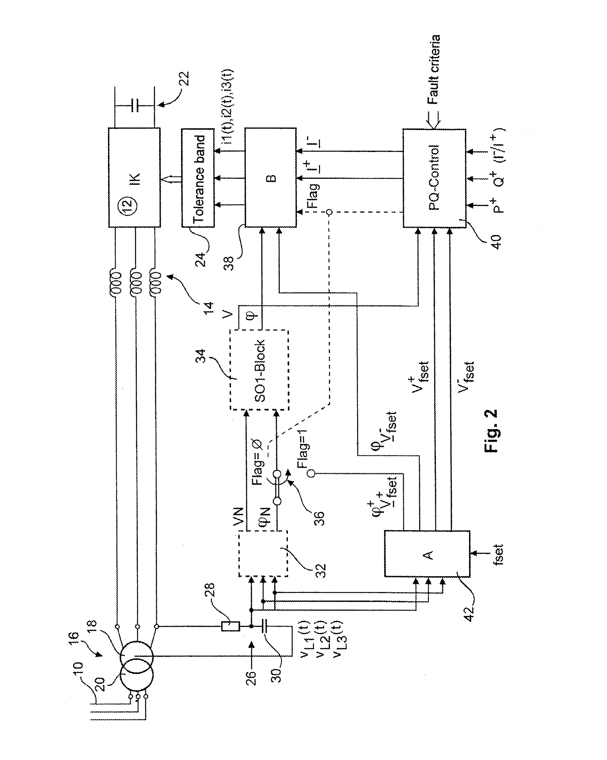
[0056]The structure of an embodiment of the invention as shown in FIG. 2 is based on a three-phase network 10 into which an inverter 12 feeds by way of output chokes 14 and by way of a transformer 16. The transformer 16 has a primary side 18 and a secondary side 20. The transformer 16 is connected to the three-phase network 10 by way of a secondary side 20 and the primary side 18 is connected to the inverter 12 by way of the output chokes 14.

[0057]The inverter 12 is supplied by way of a DC voltage intermediate circuit 22 with a direct current or a DC voltage, preferably the DC voltage intermediate circuit 22 can be fed by a wind power installation or a generator of a wind power installation, in which electric curr...


PUM


Abstract

The invention relates to a method for feeding electrical current into an electrical, three-phase power supply system having a first phase, a second phase and a third phase with a first voltage, a second voltage and a third voltage at a power supply system frequency, comprising the steps of: measuring the first, second and third voltages, transforming the first, second and third voltages into a positive phase-sequence voltage system and a negative phase-sequence voltage system according to the method of symmetrical components, calculating a first desired current, a second desired current and a third desired current for feeding into the first, second and third phases of the power supply system, wherein the first, second and third desired currents are calculated on the basis of at least one value of the positive phase-sequence voltage system and / or the negative phase-sequence voltage system.

Description

BACKGROUND[0001]1. Technical Field[0002]The present invention concerns a method and a apparatus for feeding electric current into an electric three-phase network. The present invention also concerns a wind power installation which is adapted to feed electric current into a three-phase network.[0003]2. Description of the Related Art[0004]Methods and apparatuses for feeding electric current into an electric three-phase network such as for example the European integrated network or into a part thereof are generally known. Large-scale power stations use for that purpose a synchronous generator connected directly to the electric network. For that purpose the synchronous generator is operating at a suitable rotary speed which is precisely matched to the frequency of the electric network. Depending on the respective structural configuration of the synchronous generator the rotary speed is for example 1500 revolutions per minute in the case of a four-pole synchronous generator connected to ...

Claims


Application Information

Patent Timeline
Patent Type & Authority Applications(United States)
IPC IPC(8): H02M5/40
CPCH02M5/40H02J3/26Y02E40/50H02J3/00H02J2300/28H02J3/381Y02E10/72Y02E10/76H02J3/44H02J3/48H02J3/50F03D7/0284
Inventor DIEDRICHS, VOLKERBEEKMANN, ALFRED
Owner WOBBEN PROPERTIES GMBH
Learn More