

Axial turbine
Active Publication Date: 2014-09-11
CHOI HYUK SUN
View PDF13 Cites 5 Cited by
- Summary
- Abstract
- Description
- Claims
- Application Information
AI Technical Summary
Benefits of technology
The present invention is a turbine that includes a submerged turbine, a colliding turbine, and a repulsive turbine. The technical effect of this invention is that it allows for the use of different turbines based on the field situation, maximizing the angle efficiency of blades and solving problems such as lowering temperature and applying a load to pressures. Additionally, the invention solves the problem of reducing a load on a wing caused by applied pressure.
Problems solved by technology
However, the gas turbine has a low thermal efficiency and a high lower consumption, and the structure of rotating bodies are complex and large-sized so that a wide axial space is necessary and the gas turbine cannot be easily installed.
However, the technology according to the related art also has the following problems.
That is, since the turbine does not include a submerged turbine and a colliding turbine, it cannot be selectively used in correspondence to a field situation.
Further, the technology according to the related art cannot maximize an angle efficiency of a turbine wing.
In addition, the technology cannot prevent loss of flow rate.
Furthermore, in the technology according to the related art, since a pressure of a fluid pushes down the wings, the wings may be damaged and distance efficiency cannot be maximized.
In addition, the technology according to the related art cannot solve the problem of lowering a temperature of the fluid.
Finally, the technology according to the related art fails to solve the problems of applying a load to a pressure of the wings.
Method used
View moreImage
Smart ImageViewing Examples

Examples
first embodiment
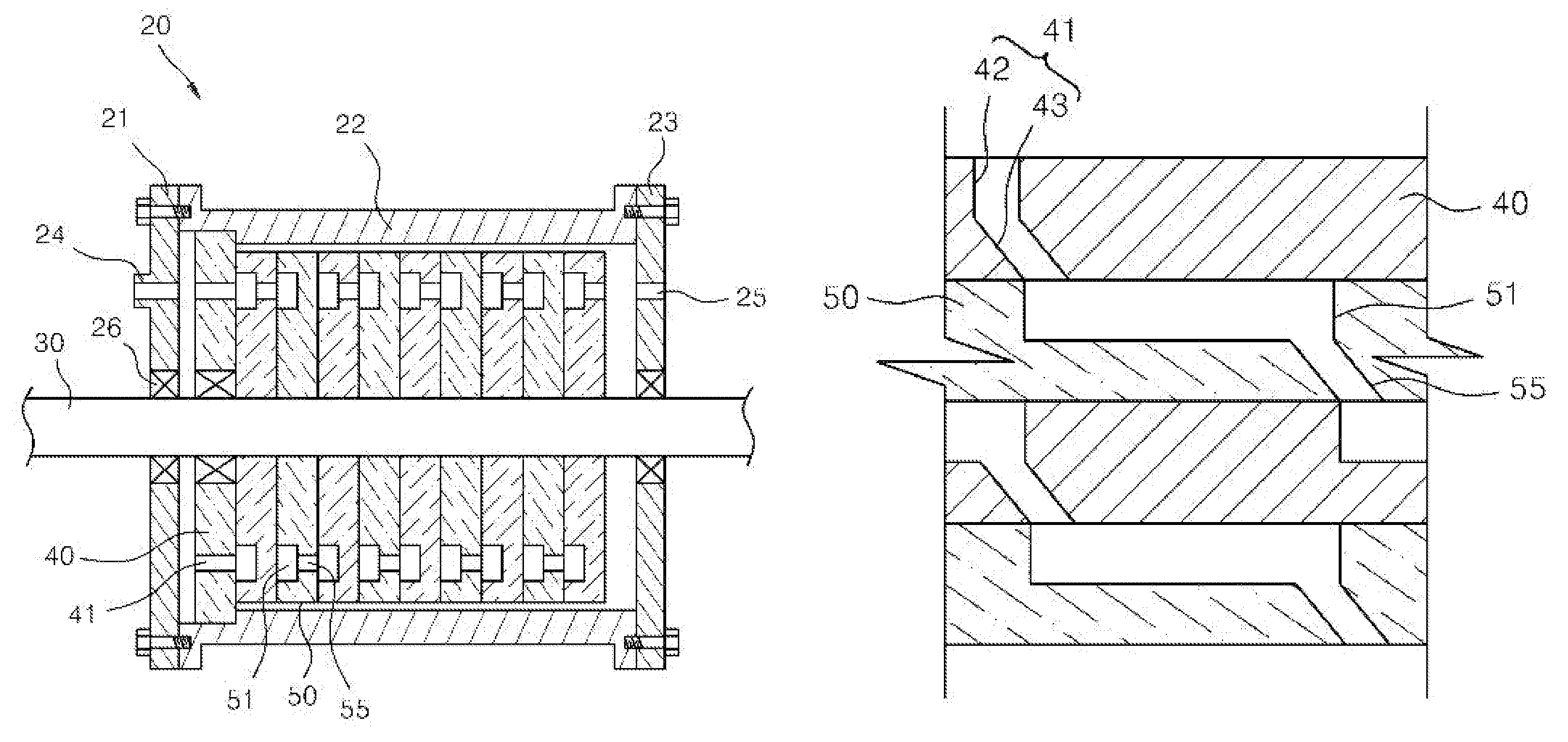
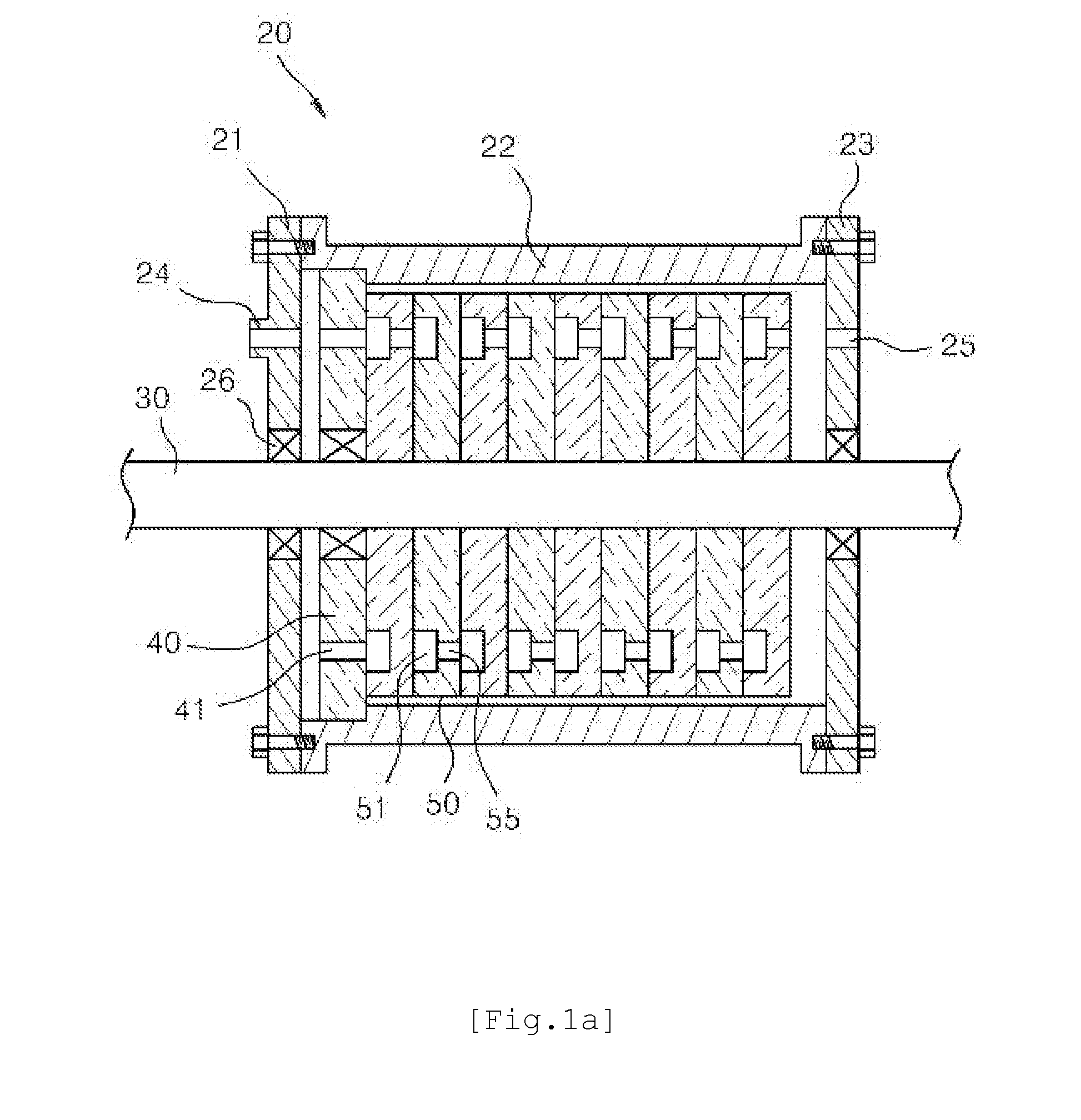
[0034]FIG. 2 is a sectional view of an axial turbine according to the present invention;
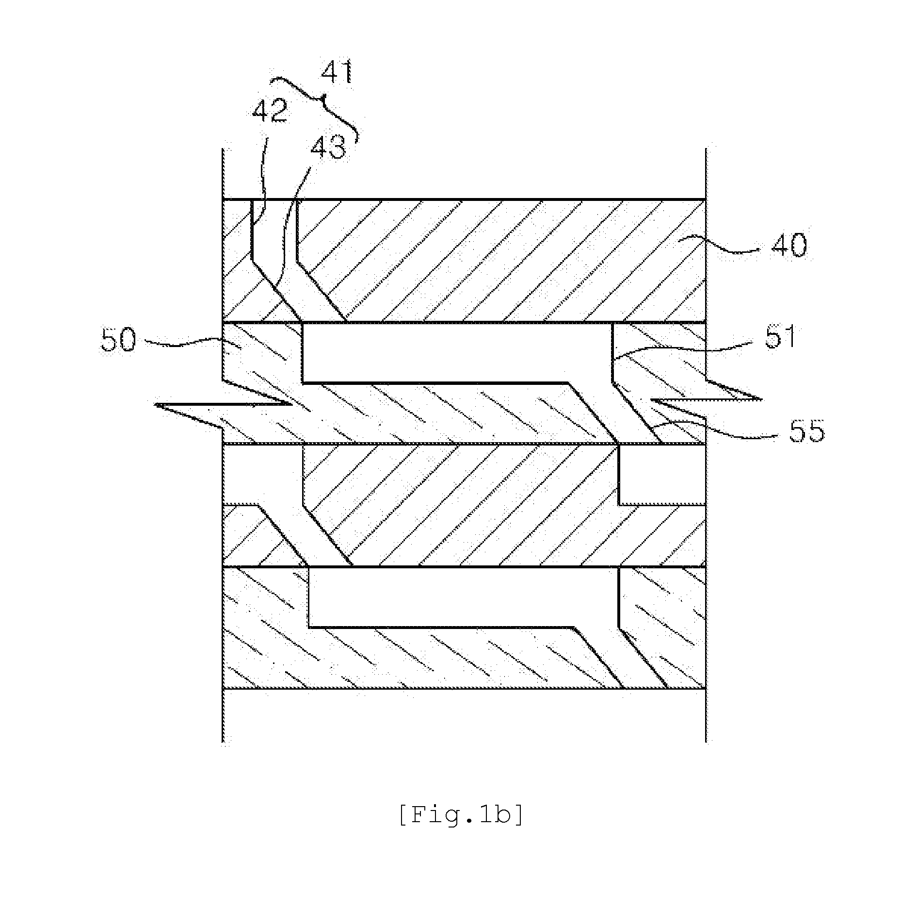
[0035]FIG. 3 is a sectional view taken along line A-A of FIG. 2;
[0036]FIG. 4 is a sectional view taken along line B-B of FIG. 2;
second embodiment
[0037]FIG. 5 is a sectional view of an axial turbine according to the present invention;
[0038]FIG. 6 is a sectional view taken along line C-C of FIG. 5;
third embodiment
[0039]FIG. 7 is a sectional view of an axial turbine according to the present invention;
Login to View More PUM
 Abstract
The present invention relates to an improvement of an axial turbine. Thereto, the present invention includes a submerged turbine 100 in which a fluid is filled in an interior thereof. The present invention also includes a colliding turbine 200 for ejecting a fluid with a high pressure to rotate blades. The structure of the turbine according to the present invention includes a submerged turbine, a colliding turbine, or a combination type turbine (in which a submerged turbine and a colliding turbine are combined). Accordingly, quality and reliability of the product are significantly improved to satisfy the operator.
Description
TECHNICAL FIELD[0001]The present invention relates to an improved structure of an axial turbine which can be arbitrarily formed in one stage or in multi-stages according to a type, a flow rate, or a head of a fluid, and more particularly to a submerged turbine, a colliding turbine, a repulsive turbine, or a combined turbine in which two of a submerged turbine, a colliding turbine, and a repulsive turbine are combined to be selectively used according to a field situation, by which quality and reliability of a product can be significantly improved to satisfy the operator.[0002]In-use ranges: gas, steam, water power, wind power, tidal current, tidal power, various power enginesBACKGROUND ART[0003]The present invention is an improvement of Korean Patent Application Publication No. 2010-0105103 (Korean Patent Application No. 2009-0023951) (entitled axial turbine) filed by the applicant.[0004]As generally known in the art, a turbine is a machine for converting the energy of a fluid such a...
Claims
Login to View More Application Information
Patent Timeline
 IPC IPC(8): F04D19/02
CPCF04D19/02F01D1/026F01D1/14F01D1/22F01D1/32F01D1/34F01D1/04F01D1/10F01D5/14
InventorCHOI, HYUK SUN
OwnerCHOI HYUK SUN