
Systems and methods for treating target tissue in the vitreous cavity

a vitreous cavity and target tissue technology, applied in the field of system and method for performing ophthalmic surgical procedures, can solve the problems of central retina, macular hole formation, and inability to precisely cut the mechanical cutting tool,

Inactive Publication Date: 2014-09-11
TECHNOLAS PERFECT VISION
View PDF3 Cites 36 Cited by
  • Summary
  • Abstract
  • Description
  • Claims
  • Application Information

AI Technical Summary

Benefits of technology

The present invention provides a system and method for treating targeted tissue in the vitreous cavity of an eye using laser technology. The laser can be controlled by a computer program to direct the focal spot of the laser beam to the targeted tissue and perform treatment / emulsification using techniques such as Optical Coherence Tomography (OCT). The system includes a laser unit, a detector, and a computer interconnected to the laser unit and detector. The computer program sets a focal spot path through the targeted tissue and the laser beam is moved to minimize any deviation from the set path. Overall, the technology allows for precise treatment and removal of tissue in the vitreous cavity without the need for mechanical cutting instruments.

Problems solved by technology

Although these conventional methods may still have some utility, the imprecision of the mechanical cutting tool limits their use.
In addition, the shrinking of the vitreous body can tear the central retina and cause a macular hole to form.
Unfortunately, the effect of these macular holes on a patient's eyesight can be rather severe.
On the other hand, some floaters can substantially affect a patient's vision.
The large ablation footprint increases the risk of collateral damage to non-target tissue.
Because of the invasiveness, risks and potential side effects associated with the current treatment techniques, many surgeons consider the risks of these procedures to be too severe to justify treatment, in all but the most severe cases.
In addition to adversely affecting a patient's vision, floaters can affect the accuracy of a surgical laser beam during procedures in which a laser beam must pass through a floater in route to a targeted treatment area.

Method used


Image

  • Systems and methods for treating target tissue in the vitreous cavity
  • Systems and methods for treating target tissue in the vitreous cavity
  • Systems and methods for treating target tissue in the vitreous cavity

Examples


Embodiment Construction

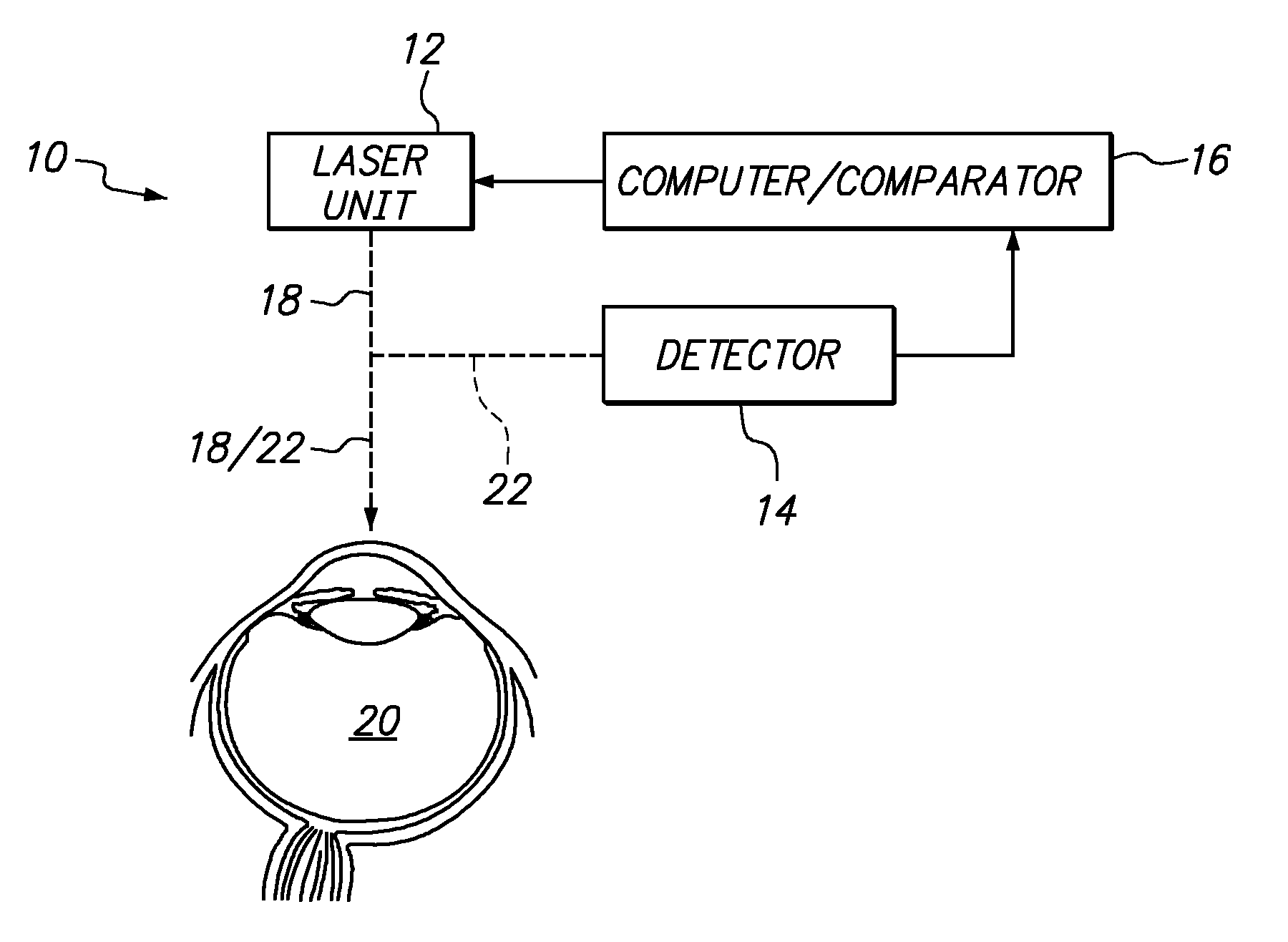
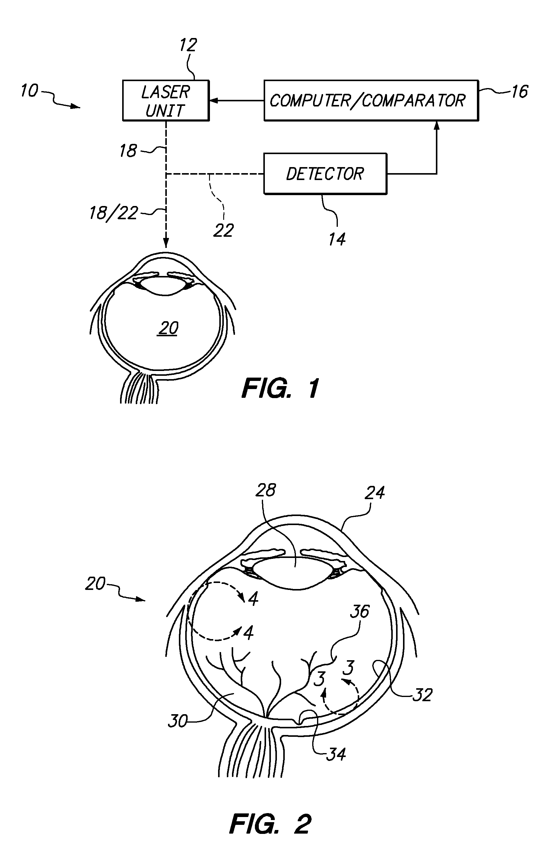
[0021]Referring initially to FIG. 1, a system for treating targeted tissue in the vitreous cavity of an eye is shown and is generally designated 10. As shown, the system 10 includes a laser unit 12, a detector 14 and a computer / comparator 16. In the system 10, the detector 14 is operationally connected to the computer / comparator 16, and the computer / comparator 16 is connected directly to the laser unit 12. With this combination, the system 10 is used to generate and direct a laser beam 18 toward an eye 20 for an ophthalmic surgical procedure as envisioned for the present invention.

[0022]For the purposes of the present invention, the laser unit 12 is capable of generating a so-called “femtosecond” laser beam 18. Thus, the generated laser beam 18 includes a sequence of laser pulses having a very ultra-short duration (e.g. less than approximately 500 fs). In addition, the laser unit 12 can include a beam steering component for moving the focal spot of the laser along a selected path to...


PUM


Abstract

A system and its method for treating targeted tissue in the vitreous cavity of an eye include a laser unit for generating a laser beam and a detector for creating an image of the targeted tissue. The system also includes a computer which defines a focal spot path for emulsifying the targeted tissue. A comparator that is connected with the computer then controls the laser unit to move the focal spot of the laser beam. This focal spot movement is accomplished to treat the targeted tissue, while minimizing deviations of the focal spot from the defined focal spot path.

Description

FIELD OF THE INVENTION[0001]The present invention pertains generally to systems and methods for performing ophthalmic surgical procedures using laser devices. More particularly, the present invention pertains to systems and methods for treating target tissue in the vitreous cavity of an eye. The present invention is particularly, but not exclusively, useful as a system and method for using an OCT guided femtosecond laser to treat target tissue in the vitreous cavity of an eye.BACKGROUND OF THE INVENTION[0002]The vitreous body (also known as vitreous humor) is a colorless, gelatinous material that fills the vitreous cavity of an eye between the lens and the fundus. At the back of the eye, the vitreous contacts the retina and keeps the retina in place by pressing the retina against the choroid. Although the vitreous body is produced by retinal cells, it contains very few cells and is mostly water (greater than 98%). Still, despite its high water content, the vitreous includes enough c...

Claims


Application Information

Patent Timeline
Patent Type & Authority Applications(United States)
IPC IPC(8): A61F9/007A61F9/008
CPCA61F9/00802A61F9/00709A61F9/00825A61F2009/00851A61F2009/00874
Inventor GRANT, ROBERT EDWARDMOSEDALE, GWILLEMMORDAUNT, DAVID
Owner TECHNOLAS PERFECT VISION
Learn More