Bone pads

a technology of bone pads and bone marrow, which is applied in the field of bone pads, can solve the problems of affecting the initial fixation of cementless implants, the inability to properly prepare the bone, and the subsequent bone resorption, so as to improve the long-term bone ingrowth/ongrowth, improve the and improve the effect of initial fixation and stability

Active Publication Date: 2014-09-11
STRYKER CORP
View PDF53 Cites 58 Cited by
  • Summary
  • Abstract
  • Description
  • Claims
  • Application Information

AI Technical Summary

Benefits of technology

[0007]The present invention includes bone preparation with designed areas having accurate tolerance profiles to enable improved initial fixation and stability for cementless implant

Problems solved by technology

These methods of bone preparation may have a negative effect on the initial fixation of a cementless implant.
If the surface does not provide a stable base for a cementless implant when initial

Method used


Image

  • Bone pads
  • Bone pads
  • Bone pads

Examples


Embodiment Construction

[0071]As used herein, the term “distal” means more distant from the heart and the term “proximal” means closest to the heart. The term “inferior” means toward the feet and the term “superior” means towards the head. The term “anterior” means towards the front part of the body or the face and the term “posterior” means towards the back of the body. The term “medial” means toward the midline of the body and the term “lateral” means away from the midline of the body.

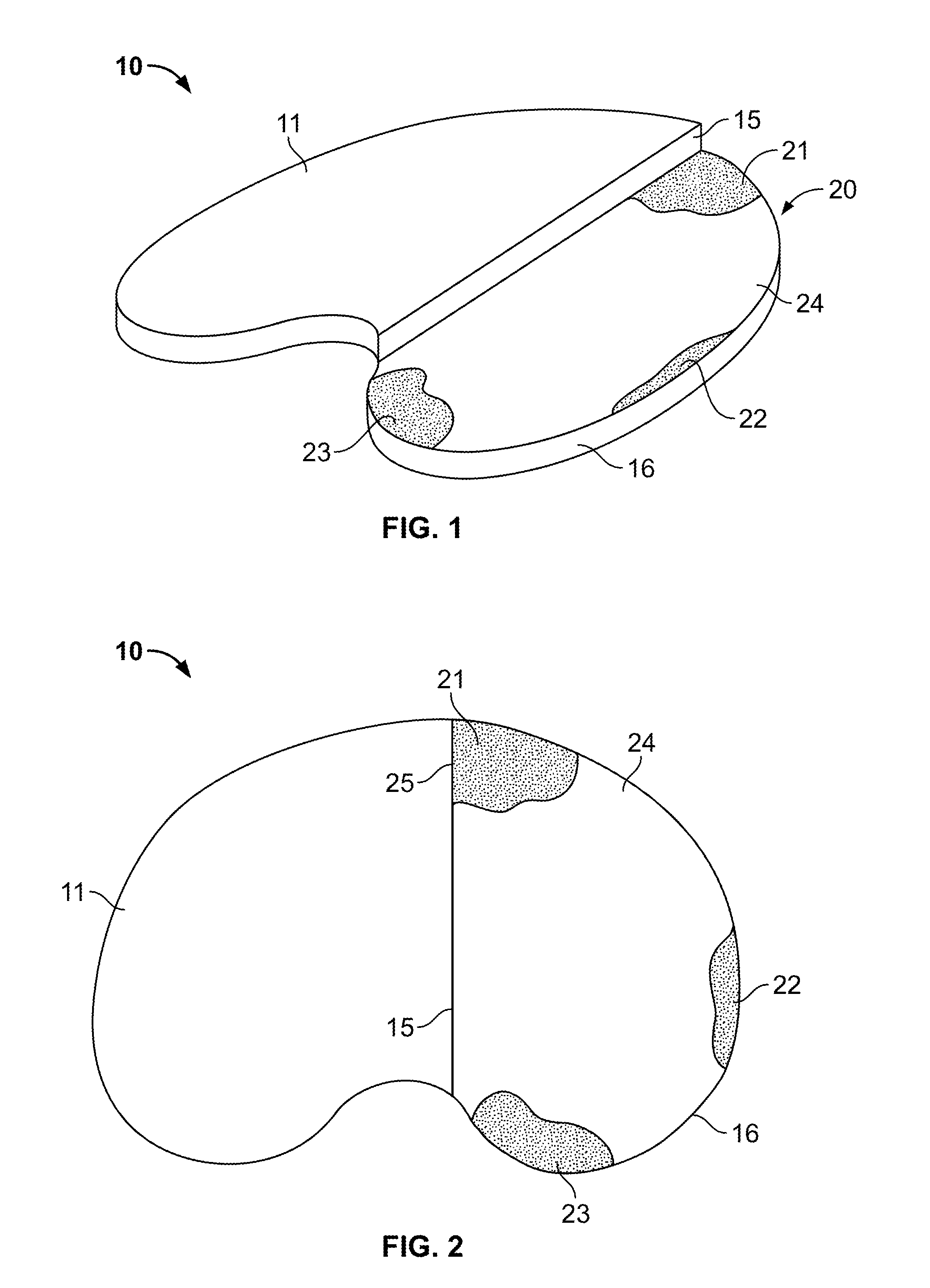
[0072]FIG. 1 illustrates a perspective view of a tibial bone 10. Bone 10 includes an unprepared region 11, a sagittal surface 15 and a transverse surface 20. Region 11 preferably retains unaltered or non-resected patient anatomy, which may include, for example, one or more of the following: articular cartilage, meniscus, and anterior and posterior cruciate ligament insertion regions. Sagittal surface 15 and transverse surface 20 represent cartilage / bone that have been prepared for an orthopedic procedure such as, for exampl...


PUM


Abstract

Disclosed herein are systems and methods for bone preparation with designed areas having accurate tolerance profiles to enable improved initial fixation and stability for cementless implants and to improve long-term bone ingrowth/ongrowth to an implant. A method of preparing a bone surface to receive a prosthetic implant thereon having an articular surface and a bone contacting surface includes resecting the bone surface at a first location to create a first resected region having a first tolerance profile with a first cross-section, resecting the bone surface at a second location to create a second resected region having a second tolerance profile with a second cross-section less dense than the first cross-section, and contacting the bone contacting surface of the prosthetic implant with the first resected region.

Description

CROSS-REFERENCE TO RELATED APPLICATIONS[0001]The present application claims the benefit of the filing date of U.S. Provisional Patent Application No. 61 / 775,045, filed Mar. 8, 2013, the disclosure of which is hereby incorporated herein by reference.BACKGROUND OF THE INVENTION[0002]In a traditional knee arthroplasty surgery, the diseased bone and / or cartilage of a patient is generally removed and replaced with a prosthetic implant. A surgeon may prepare the bone using a hand-held oscillating saw blade, for instance, which generally results in a series of planar bone surface resections. Additionally, the surgeon may use a drill, broach or tamp instrument to make cylindrical holes into the bone to accommodate peg fixation features on the implant. The planar bone resections and cylindrical bone holes are generally oriented to interface with generally flat bone contacting surfaces and pegs of a prosthetic implant.[0003]In such arthroplasty surgeries, the cartilage and / or bone of a patien...

Claims


Application Information

Patent Timeline
IPC IPC(8): A61F2/46A61B17/16
CPCA61B17/1675A61F2/461A61B17/1604A61B17/1615A61F2/3859A61F2/30771A61F2/389A61F2002/30807A61F2002/30827A61F2002/30884A61F2002/3895A61F2002/4631A61F2002/30321A61F2002/30322A61F2/46
Inventor AXELSON, JR., STUART L.MALACKOWSKI, DONALD W.
Owner STRYKER CORP
Why Eureka
Try Eureka