Vehicle control device, vehicle, and vehicle control method

a technology for vehicle control and control devices, applied in vehicle components, electric/fluid circuits, instruments, etc., can solve the problems of engine restart due to a shortage of soc, etc., to achieve the effect of improving the fuel efficiency of vehicles

Active Publication Date: 2014-09-11
TOYOTA JIDOSHA KK
View PDF13 Cites 13 Cited by
  • Summary
  • Abstract
  • Description
  • Claims
  • Application Information

AI Technical Summary

Benefits of technology

[0007]The present invention has been made to solve at least a part of the above conventional p...

Problems solved by technology

In the above technology, however, when the amount of electric power that is stored in the battery is consumed by auxiliary machines while the engine is kept stopped by idling stop control, the engine may be restarted because of a shortage of SOC (State of Ch...

Method used


Image

  • Vehicle control device, vehicle, and vehicle control method
  • Vehicle control device, vehicle, and vehicle control method
  • Vehicle control device, vehicle, and vehicle control method

Examples


modification 1

[0103]

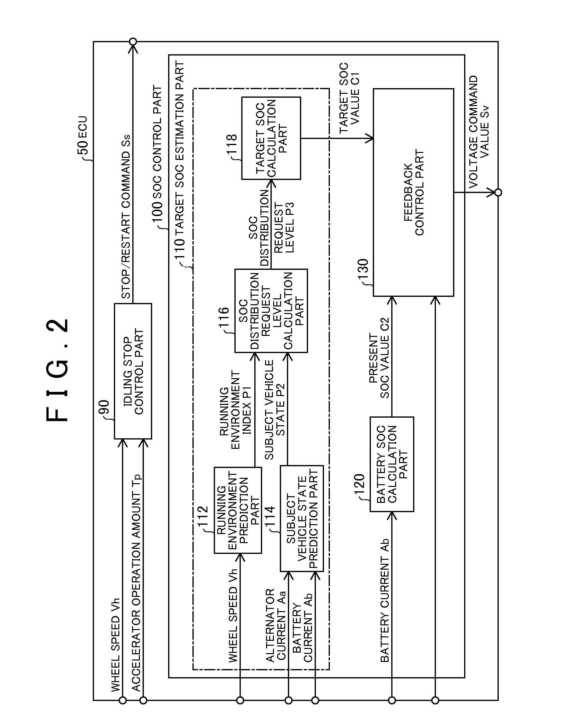
[0104]While the SOC distribution request level P3 is obtained based on the running environment index P1 and the subject vehicle state P2 in the above examples, the SOC distribution request level P3 may instead be configured to be obtained based on the amount of operation of a dial that is provided on the instrument panel (not shown) of the automobile 200 for operation by the driver. When the automobile 200 travels into an urban area from a suburban area, for example, the driver can increase the target SOC, in other words, the distribution rate for idling stop, by turning the dial to “High” to change the setting so that the SOC distribution request level P3 can increase. According to this configuration, when the driver can recognize the area which the automobile 200 will enter from now sufficiently to set the SOC distribution request level, the maximum SOC that will be used in a stop and start period can be set with a high degree of accuracy based on the running environment. Th...

modification 2

[0105

[0106]While the SOC distribution request level P3 is configured to be obtained based on the running environment index P1 and the subject vehicle state P2 and then the target SOC is configured to be calculated based on the SOC distribution request level P3 in the above examples, the target SOC may instead be configured to be directly calculated based on the running environment index P1 and the subject vehicle state P2. In other words, the distribution ratio at which the usable SOC range of the battery is distributed between a capacity for charge control and a capacity for idling stop may be configured to be directly calculated based on the running environment index P1 and the subject vehicle state P2. Similarly, the target SOC may be configured to be directly calculated based on the amount of operation of the dial in the above modification 1.

modification 3

[0107]

[0108]While the SOC distribution request level is calculated based on both the running environment index P1 and the subject vehicle state P in the above examples, the SOC distribution request level may instead be configured to be calculated based on either the running environment index P1 or the subject vehicle state P.


PUM


Abstract

To further improve fuel efficiency of vehicles. A vehicle control device that is mounted on a vehicle that has an engine, and a battery that can be charged by the amount of electric power that is generated by an alternator that is driven by power from the engine. The vehicle control device includes an idling stop control part 90, a battery SOC calculation part 120 that obtains the SOC of the battery, a target SOC estimation part 110 that sets a capacity for idling stop that is predicted to be used in a stop and start period between stop and restart of the engine by the idling stop control within the usable SOC range of the battery while the vehicle is running; and a remaining capacity control part 130 that controls the amount of electric power that is generated by the alternator to prevent the remaining capacity in the usable SOC range from falling below the capacity for idling stop while the vehicle is running that corresponds to the SOC.

Description

TECHNICAL FIELD[0001]The present invention relates to a vehicle control device that is mounted on a vehicle that has an engine and a battery, a vehicle, and a vehicle control method.BACKGROUND ART[0002]An engine and a battery are mounted on an automobile, and the battery is charged using power from the engine. Conventionally, as charge control that is performed to charge a battery, a technology to reduce the charge to the battery to reduce fuel consumption during normal running and to charge the battery by regenerative electric power generation during deceleration is known.[0003]As control that reduces fuel consumption, idling stop (also referred to as idle reduction) control is known. In Patent Literature 1 below, an automobile is disclosed that is provided with both a charge control function and an idling stop control function to meet a demand for improving fuel efficiency.[0004]In the above technology, however, when the amount of electric power that is stored in the battery is co...

Claims


Application Information

Patent Timeline
IPC IPC(8): B60R16/033
CPCB60R16/033F02D29/02B60W30/18018B60W2510/244B60W10/06B60W10/30B60W2710/244
Inventor UEKI, NOBUKAZUITO, KOJIMIYASHITA, MICHIHIROTOCHIGI, KOUHEI
Owner TOYOTA JIDOSHA KK
Why Eureka
Try Eureka