Support structures on roofs

a technology for supporting structures and roofs, applied in roofs, skylights/domes, building components, etc., can solve the problems of high stress on joints, leakage of water around the perimeter of conventional roof curbs, and all known conventional structures have a tendency to leak water, so as to reduce the number of incidents of water leakage, especially leakage about the mounting structure,

Active Publication Date: 2014-09-18
T&M INVENTIONS
View PDF5 Cites 32 Cited by
  • Summary
  • Abstract
  • Description
  • Claims
  • Application Information

AI Technical Summary

Benefits of technology

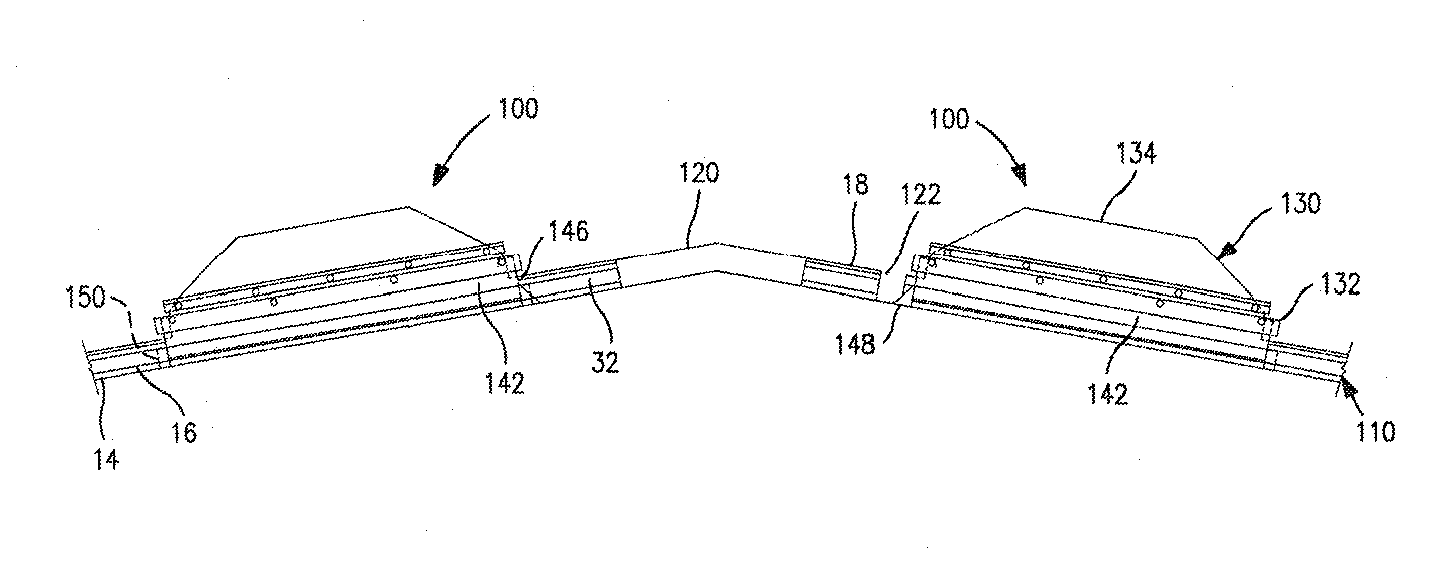
[0018]The invention provides a curbless construction system for installing roof load supports such as roof closure structures, optionally skylights and/or smoke vents, optionally including two or more such cover structures in end-to-end relationship, onto the major rib elevations of a building's metal roof panel system, thereby utilizing the beam strength of the roof rib elevations on the surface of the roof, as the support for such loads. Where skylight assemblies are placed in end-to-end relationship over a common roof aperture, the upper diverter and lower closure at the facing ends of such skylight assemblies are optionally replaced with male and female mating strips. Numerous roof structures

Problems solved by technology

Fitting skylight assemblies into such roof aperture, in a separately-mounted roof structure, presents problems in that all known conventional structures have a tendency to leak water when subjected to rain.
One of the causes of roof leaks around the perimeter of conventional roof curbs which attach primarily through the panel flat at the water line are due to foot traffic, such as heel loads or other dynamic loads imposed by workers wheeling gas cylinders or other heavy equipment on the roof panel e.g. with dollies.
This type of dynamic loading can cause high levels of stress o

Method used


Image

  • Support structures on roofs
  • Support structures on roofs
  • Support structures on roofs

Examples


Embodiment Construction

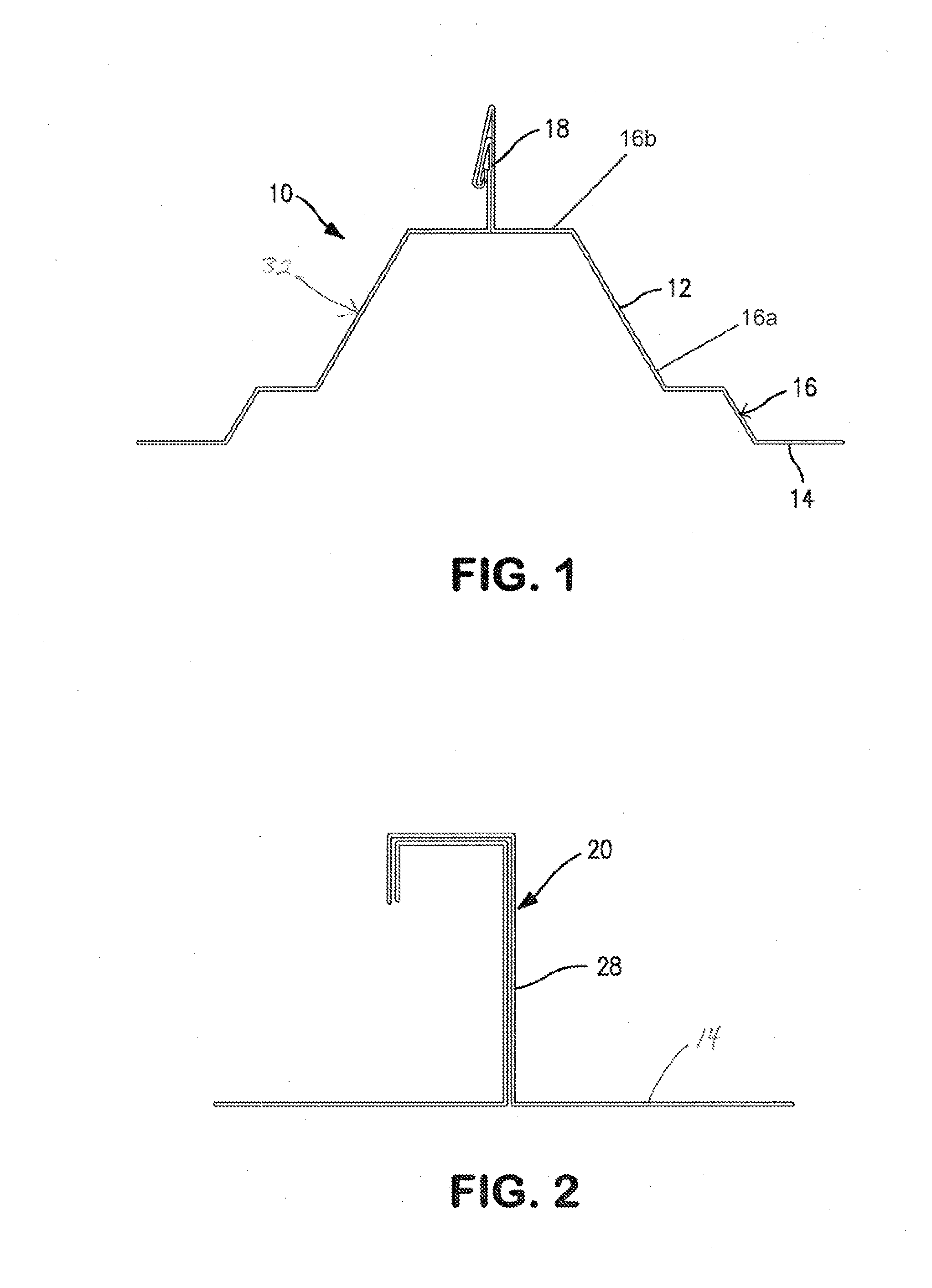
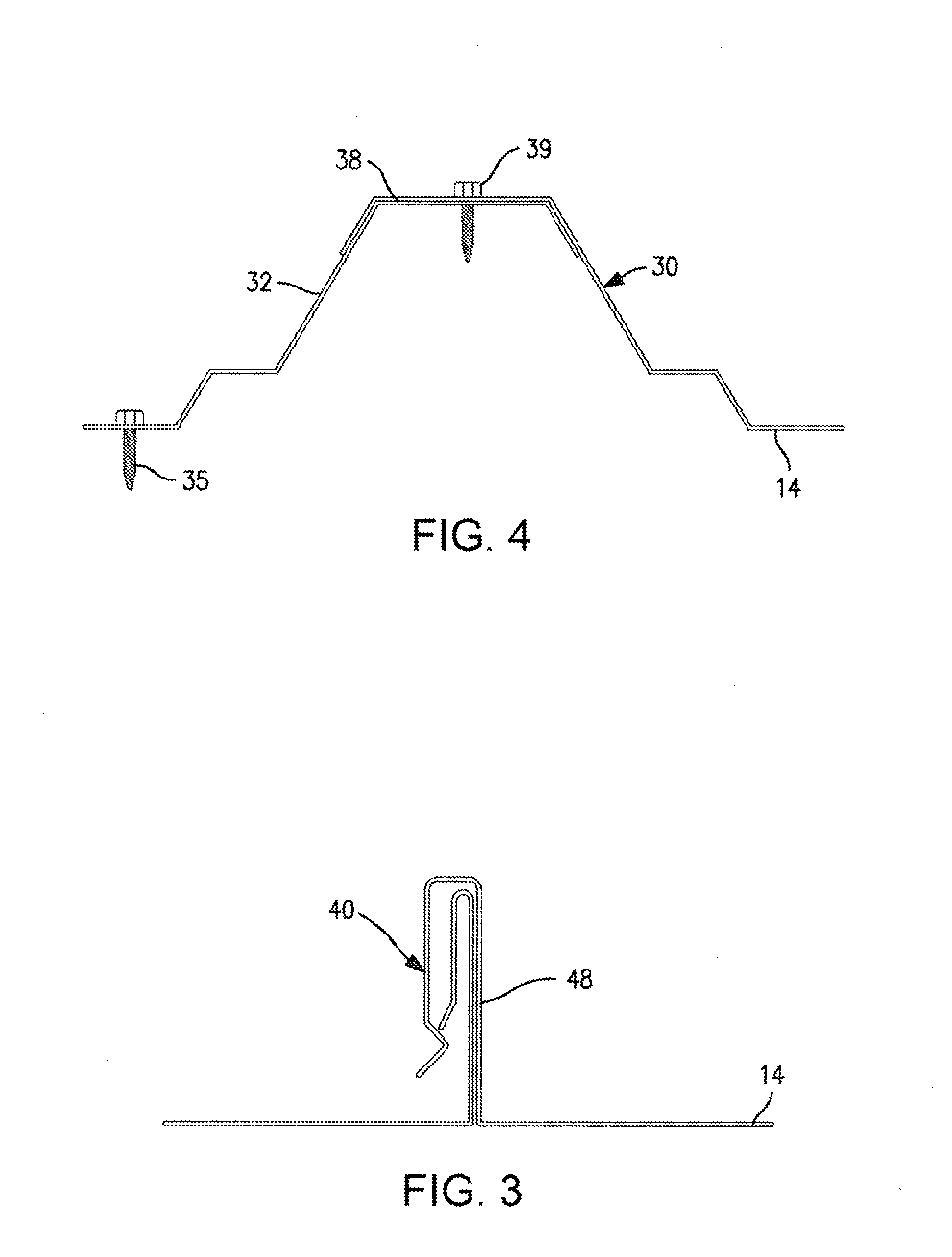
[0075]The products and methods of the present invention provide a load support structure, for use in installing various exterior roof loads which close off apertures in metal roofs. For purposes of simplicity, “load support structure” will be used interchangeably to mean various forms of closed-perimeter structures which are mounted on ribs of raised elevation metal roof structures, which surround an aperture in a roof, including across the flat of a roof panel, and which support either a cover over the aperture, or a vent or other conduit which extends through the roof aperture. Skylight assemblies and smoke vents are non-limiting examples of covers over such roof apertures. Air handling operations such as vents, air intakes, and air or other gaseous exchange to and / or from the interior of the building are non-limiting examples of operations where conduits extend through the roof aperture. In the case of roof ventilation, examples include simple ventilation openings, such as for ro...


PUM


Abstract

Metal panel roofs, and load support structures for supporting loads on such roofs. Side rails provide primary support for loads on such roofs. The side rails can be fabricated from sheet metal or can be extruded. A side rail includes a standing seam cavity which is lowered, and covers, the standing seam. Side walls of the standing seam cavity. An upstanding web extends up from the cavity, and lower shoulders may extend laterally, optionally downwardly, from the walls which define the cavity, on either one side, or both sides, of the cavity. Building roof insulation can extend up through an aperture in the roof, surrounded by such load support structure, and extend up to the top of the side rail, thus providing a thermal break between the load support structure elements and the space surrounded by the load support structure.

Description

BACKGROUND OF THE INVENTION[0001]Various systems are known for supporting loads on roofs, and for installing skylights and / or smoke vents into roofs.[0002]Commonly used skylighting systems have translucent or transparent closure members, also known as lenses, mounted on a support structure which extends through an aperture in the roof and is mounted to building support members inside the building. Ambient daylight passes through the lens and thence through the roof aperture and into the building.[0003]Thus, conventional skylight and smoke vent installations use a complex structure beneath the exterior roofing panels and inside the building enclosure, in order to support a curb which extends through the roof and supports the skylight lens. Conventional skylight curbs, thus, are generally in the form of a preassembled box structure surrounding an aperture which extends from the top of the box structure to the bottom of the box structure. Such box structure is mounted to building frami...

Claims


Application Information

Patent Timeline
IPC IPC(8): E04D13/03
CPCE04D13/031E04D3/364E04D13/0315
Inventor PENDLEY, TIMOTHYMCLAIN, MICHAEL J.
Owner T&M INVENTIONS
Why Eureka
Try Eureka