Evacuated tube transport system with improved cooling for superconductive elements

a superconductive element and transport system technology, applied in transportation and packaging, propulsion railway systems, transportation and packaging, etc., can solve the problems of transportation construction and operating costs, not yet widely commercialized, etc., and achieve the effects of reducing magnetic drag forces, improving lightning protection, and reducing electrical conductivity

Inactive Publication Date: 2014-09-18
OSTER DARYL
View PDF15 Cites 30 Cited by
  • Summary
  • Abstract
  • Description
  • Claims
  • Application Information

AI Technical Summary

Benefits of technology

[0019]The present invention focuses on the field of automated transportation of goods and passengers in magnetically levitated capsules independently operating in evacuated tubes. The field has not yet been widely commercialized; however it has the potential to dramatically reduce transportation construction and operating costs if properly optimized for maximum transportation value. In particular, significant cost savings are realized through transportation energy efficiency. Other cost savings are realized by lowering the capital costs for construction.
[0044]In one embodiment, a portion, up to half, of the superconductor levitation force material is replaced with permanent magnet material that is oriented in attraction in the upper cryostat and is oriented in repulsion in the lower cryostat such that sufficient stability is maintained at reduced cost.

Problems solved by technology

The field has not yet been widely commercialized; however it has the potential to dramatically reduce transportation construction and operating costs if properly optimized for maximum transportation value.

Method used


Image

  • Evacuated tube transport system with improved cooling for superconductive elements
  • Evacuated tube transport system with improved cooling for superconductive elements
  • Evacuated tube transport system with improved cooling for superconductive elements

Examples


Embodiment Construction

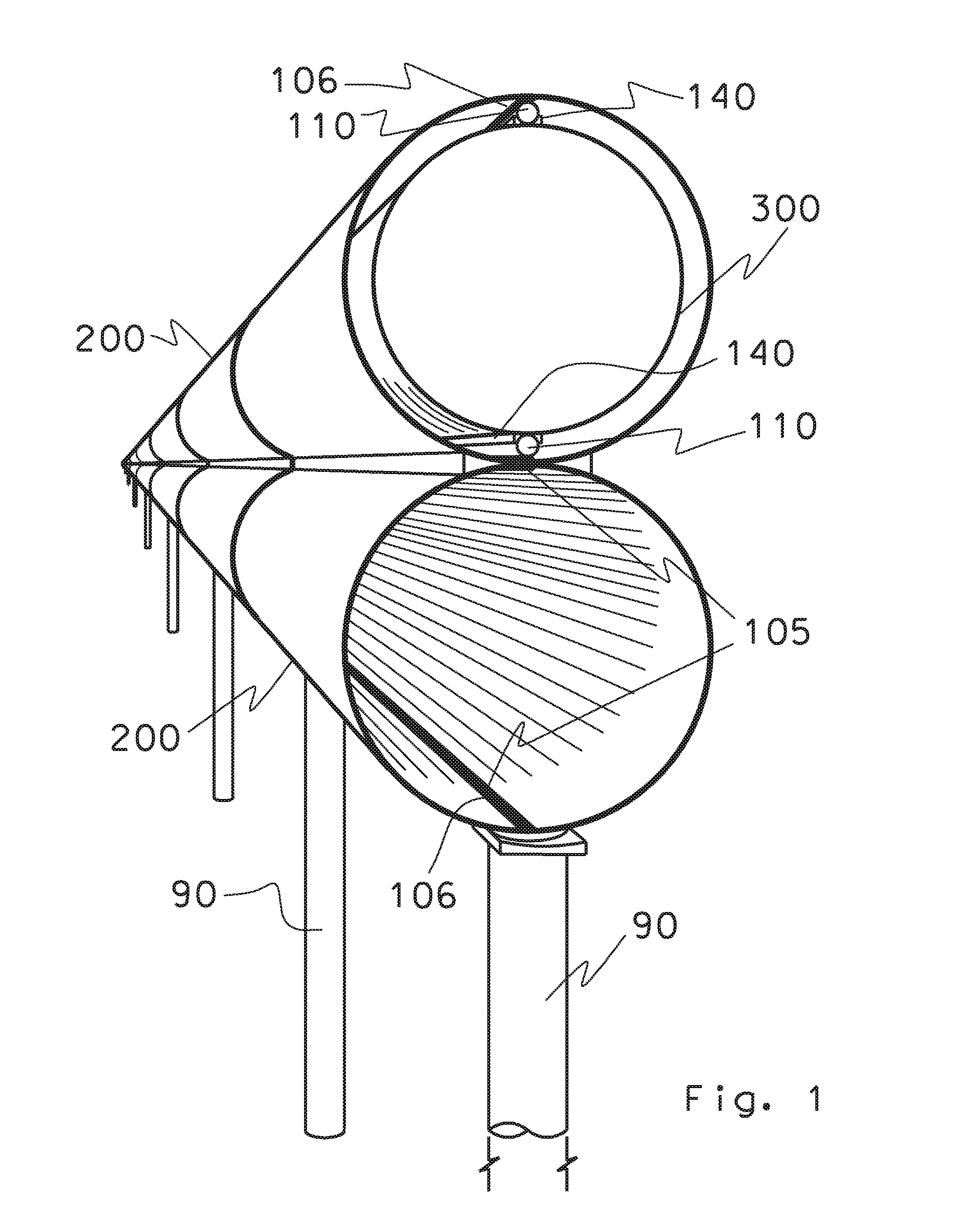
[0058]FIG. 1 shows a pair of tubes 200 stretching across a landscape. The tubes mount on concrete pillars 90 and are shown above ground. Above-ground construction reduces costs and eases maintenance and inspections. It can be appreciated that below ground and underwater mounting of the tubes 200 is also viable in accordance with the present invention.

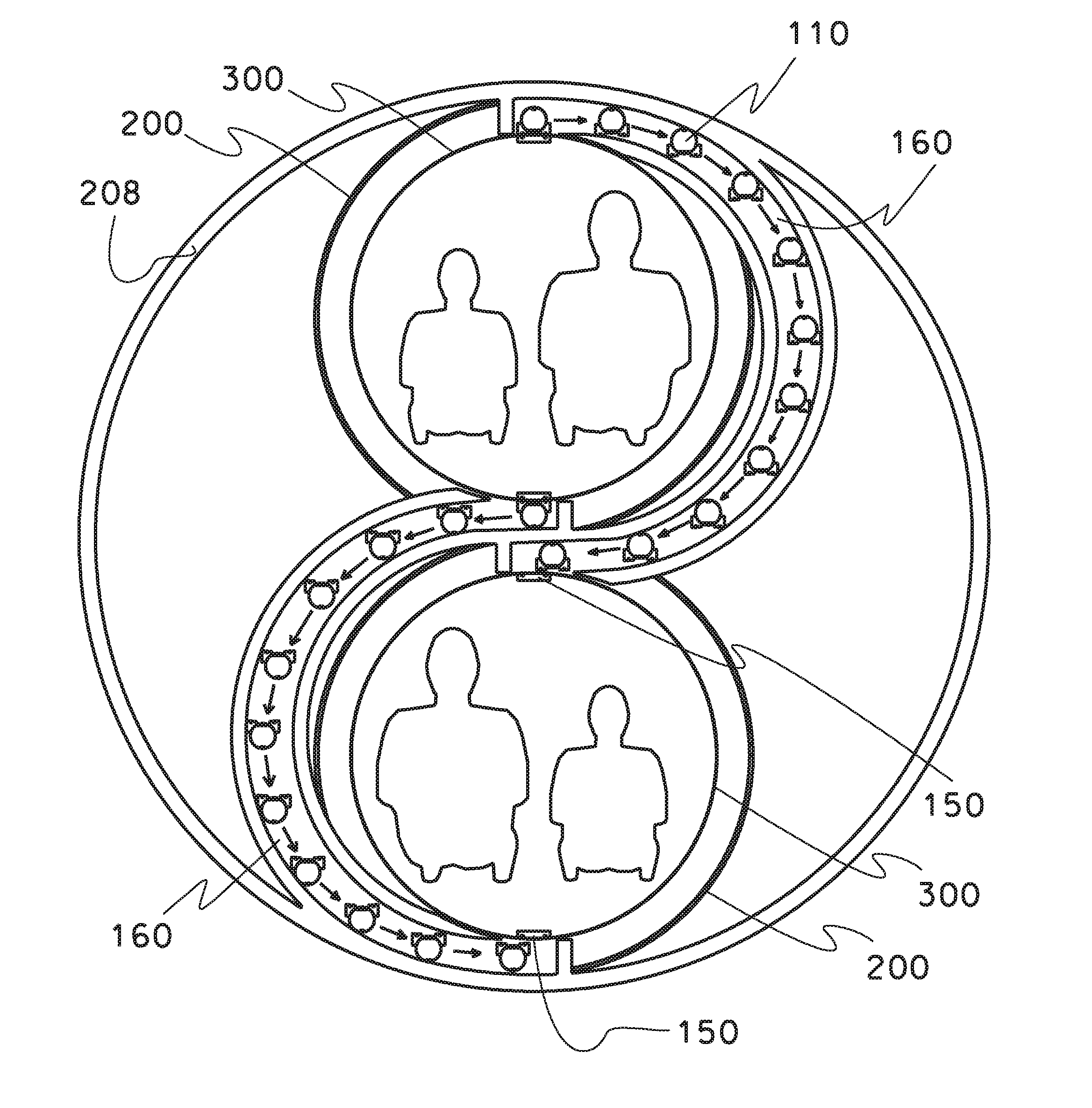
[0059]The pair of tubes 200 enables simultaneous transport of capsules 300 in opposite directions.

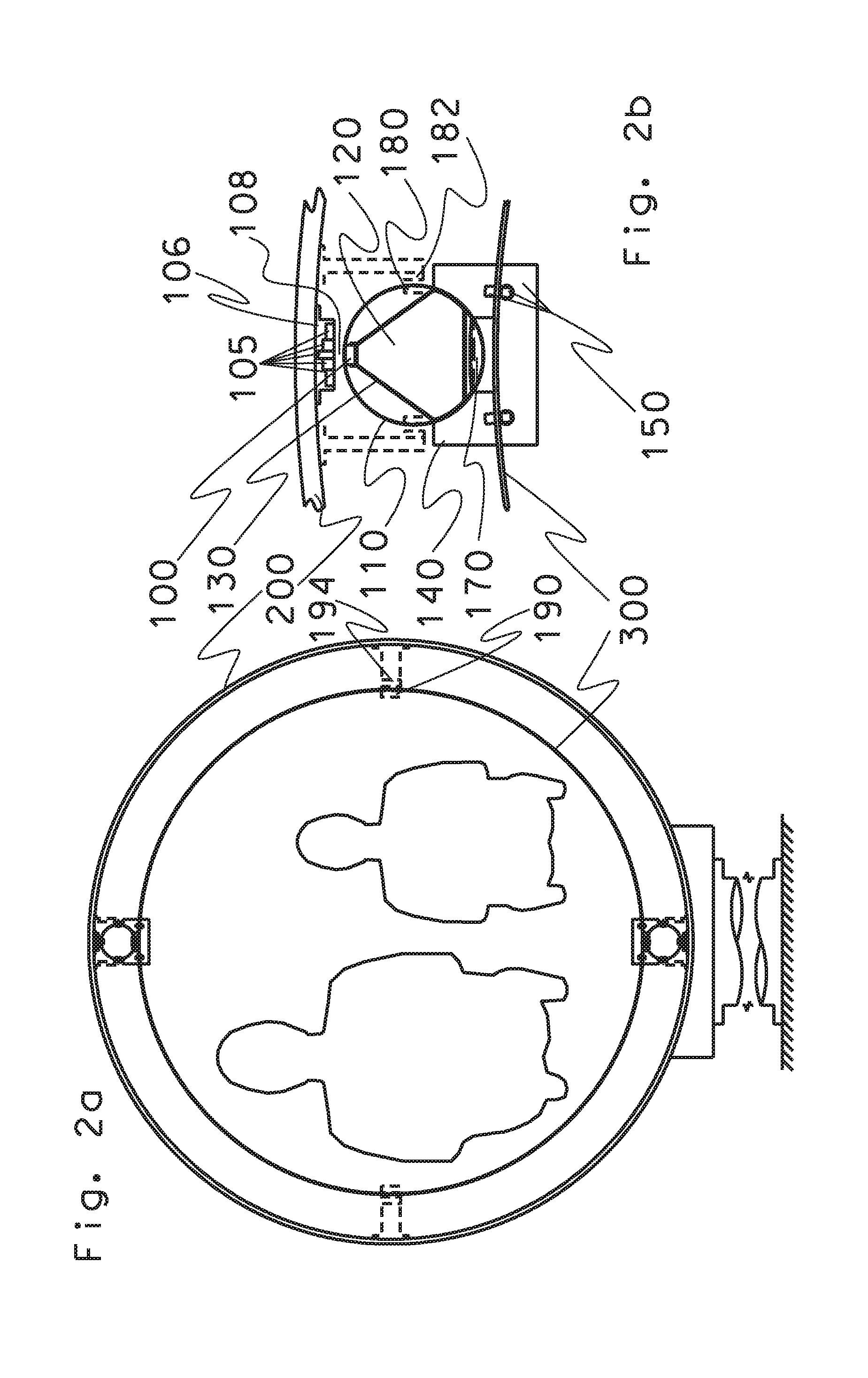
[0060]FIG. 2a shows a cross-section of a capsule 300. The capsule 300 levitates in the tube 200. The tube includes diverge force elements 194. The capsule 300 includes switchable diverge force elements 190.

[0061]The tube 200 has a circular cross-section and sized having a diameter to accommodate two passengers seated shoulder-to-shoulder. A superconductor (SC) element 100 mounts in opposing arrangement on the external surface of the capsule 300.

[0062]FIG. 2b shows a cross-section of the superconductor (SC) element 100, which includes perman...


PUM


Abstract

A High Temperature Superconductor Maglev (HTSM) for Evacuated Tube Transport (ETT) with a magnetic levitation structure for ETT capsule vehicles traveling in an evacuated tube. At least one ETT capsule travels within an evacuated tube, an upper and a lower cryostat respectively mount at the top and bottom of said ETT capsule along the length thereof, at least a plurality of superconductor levitation force elements divided between said upper and lower cryostats. The levitation force being spread over the length of capsule, however substantially concentrated in a compact cross-sectional area. At least a pair of permanent magnetic elements mounted at the top and bottom of the evacuated tube to cooperate with the superconductor elements to levitate the capsule.

Description

INCORPORATION BY REFERENCE[0001]U.S. Pat. No. 5,950,543 issued 14 Sep. 1999 is incorporated herein by reference.FIELD OF THE INVENTION[0002]The present invention relates to rapid transit utilizing magnetically levitated vehicle suspension, and particularly to energy efficient evacuated tube-transport systems.BACKGROUND OF THE INVENTION[0003]Automated Personal Rapid Transit (PRT), where automobile sized (or smaller) vehicles independently operate on fixed rails. Most PRT system designs use passive rails (analogous to freeways) that rely on steering equipment in the vehicle to affect divergence to an alternative branch (analogous to an exit on a freeway).[0004]The field of magnetically levitated vehicle suspension (maglev) includes a variety of technologies in the market. Most maglev vehicle suspension technologies have been optimized for use in trains; several rely upon active (mechanically movable) switch elements.[0005]Train-type mechanical switch elements are limited in quickness,...

Claims


Application Information

Patent Timeline
Patent Type & Authority Applications(United States)
IPC IPC(8): B61B13/10
CPCB61B13/10B61B13/08E01B25/30Y02T30/00B60L13/04B60L13/10B60L2200/26B61B13/12
Inventor OSTER, DARYL
Owner OSTER DARYL
Why Eureka
Try Eureka