Substrate treatment apparatus and substrate treatment method

a substrate treatment and substrate technology, applied in the direction of cleaning process and apparatus, chemistry apparatus and processes, cleaning using liquids, etc., can solve the problems of substrate damage spraying region is liable to have a portion not formed, etc., to suppress the damage of the substrate

Inactive Publication Date: 2014-09-18
DAINIPPON SCREEN MTG CO LTD
View PDF6 Cites 14 Cited by
  • Summary
  • Abstract
  • Description
  • Claims
  • Application Information

AI Technical Summary

Benefits of technology

[0016]As a result, the spraying region can be entirely covered with the protection liquid film by supplying the protection liquid at a lower flow rate to the substrate irrespective of the position of the

Problems solved by technology

Therefore, the spraying region is liable to have a portion not formed with a sufficiently thick protection liquid film.
If the treatment liquid droplets are sprayed to the spraying region having a portion uncovered wit

Method used


Image

  • Substrate treatment apparatus and substrate treatment method
  • Substrate treatment apparatus and substrate treatment method
  • Substrate treatment apparatus and substrate treatment method

Examples


first embodiment

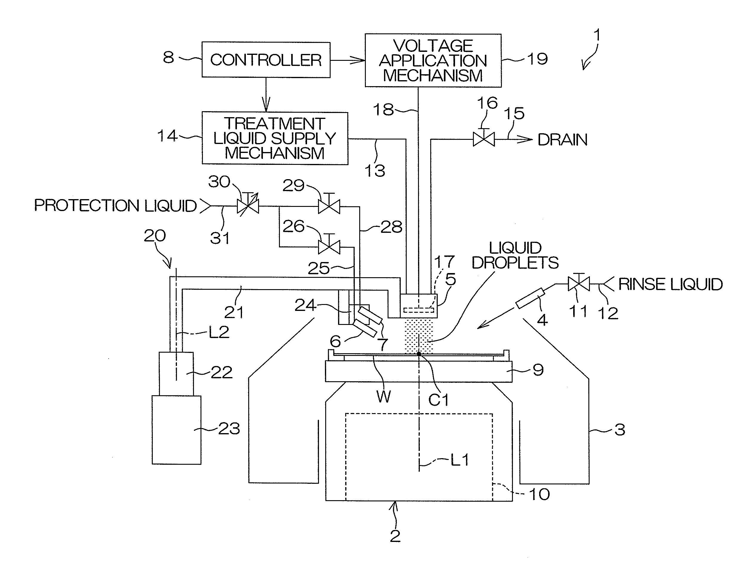
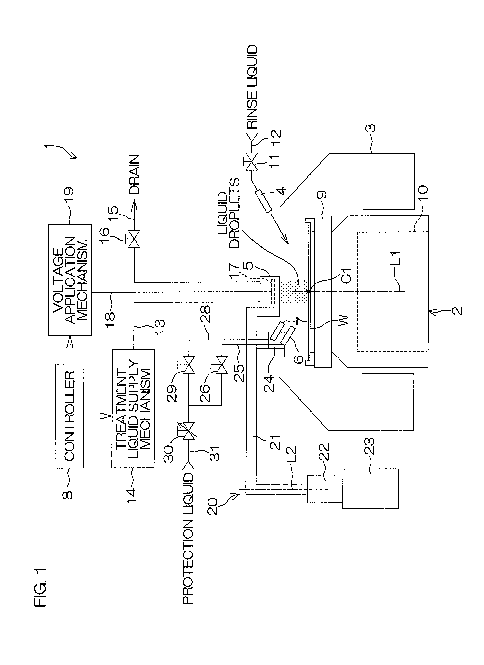
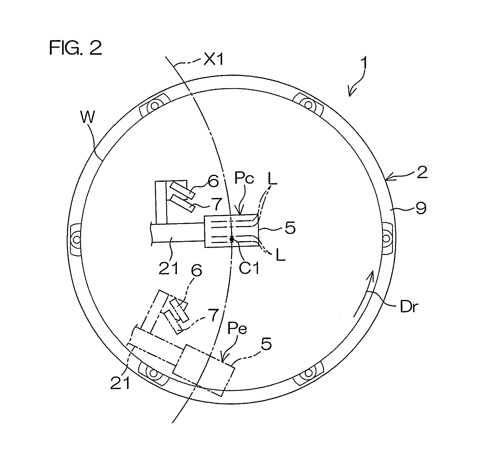
[0097]FIG. 1 is a diagram schematically showing the construction of a substrate treatment apparatus 1 according to the present invention. FIG. 2 is a plan view showing a liquid droplet nozzle 5 and an arrangement related to the liquid droplet nozzle.

[0098]The substrate treatment apparatus 1 is of a single substrate treatment type adapted to treat a single disk-shaped substrate W (e.g., semiconductor wafer) at a time. The substrate treatment apparatus 1 includes a spin chuck 2 (substrate holding unit) which horizontally holds and rotates the substrate W, a tubular cup 3 which surrounds the spin chuck 2, a rinse liquid nozzle 4 which supplies a rinse liquid to the substrate W, a liquid droplet nozzle 5 which causes droplets of a treatment liquid to impinge on the substrate W, a first protection liquid nozzle 6 which supplies the protection liquid to the substrate W, a second protection liquid nozzle 7 which supplies the protection liquid to the substrate W, and a controller 8 which co...

second embodiment

[0258]FIGS. 23A to 23F are diagrams for explaining a fifth exemplary treatment process to be performed on the substrate W by the substrate treatment apparatus 201 according to the present invention.

[0259]In the fifth exemplary treatment process, only a cleaning step and a second covering step are different from those of the first exemplary treatment process to be performed by the substrate treatment apparatus 1. Since the other steps are performed in the same manner as in the first exemplary treatment process, duplicate description will be omitted. Referring to FIGS. 18 to 23F, the cleaning step and the second covering step of the fifth exemplary treatment process will be described.

[0260]As shown in FIG. 23A, the controller 8 controls the nozzle movement mechanism 20 to move the liquid droplet nozzle 5 and the third protection liquid nozzle 206 from home positions (not shown) defined outside the rotation range of the substrate W to above the spin chuck 2, and locate the lower surfac...


PUM


Abstract

The inventive substrate treatment apparatus includes a change controlling unit which changes at least one of a protection liquid application position relative to a liquid droplet nozzle and a protection liquid incident angle relative to the liquid droplet nozzle, the protection liquid application position being a position at which the protection liquid is applied on an upper surface of the substrate, the protection liquid incident angle being an angle at which the protection liquid is incident on the liquid application position; wherein the change controlling unit controls the liquid application position and the incident angle in a first condition when the spraying region is located on an upper surface center portion of the substrate, and controls the liquid application position and the incident angle in a second condition when the spraying region is located on an upper surface peripheral portion of the substrate.

Description

BACKGROUND OF THE INVENTION[0001]1. Field of the Invention[0002]The present invention relates to a substrate treatment apparatus and a substrate treatment method. Exemplary substrates to be treated include semiconductor wafers, substrates for liquid crystal display devices, substrates for plasma display devices, substrates for FED (Field Emission Display) devices, substrates for optical disks, substrates for magnetic disks, substrates for magneto-optical disks, substrates for photo masks, ceramic substrates and substrates for solar cells.[0003]2. Description of Related Art[0004]In production processes for semiconductor devices, liquid crystal display devices and the like, substrates such as semiconductor wafers and glass substrates for the liquid crystal display devices are treated with a treatment liquid.[0005]A substrate treatment apparatus of a single substrate treatment type adapted to treat a single substrate at a time includes a spin chuck which horizontally holds and rotates ...

Claims


Application Information

Patent Timeline
IPC IPC(8): B08B3/04
CPCB08B3/04H01L21/67028H01L21/67051B08B3/041
Inventor SOTOKU, KOTATANAKA, TAKAYOSHISATO, MASANOBU
Owner DAINIPPON SCREEN MTG CO LTD
Why Eureka
Try Eureka