Boring bit and method of manufacture

a technology of boring bits and manufacturing methods, applied in the field of boring bits, can solve the problems of not providing a good temporary connection, carbide teeth are not typically formed in situ, and the fluid does not provide any significant assistance in the steering of the head, so as to achieve the effect of loosening the temporary connection

Inactive Publication Date: 2014-09-18
ROCKHOUND BORING PROD LLC DBA US DRILLING PROD
View PDF4 Cites 2 Cited by
  • Summary
  • Abstract
  • Description
  • Claims
  • Application Information

AI Technical Summary

Benefits of technology

[0011]In another aspect of the invention, stabilizing rods are welded to the tips of the teeth to form a temporary connection, and the core body is formed from a molten metal poured into a cavity of a cast mold. The stabilizing rods are inserted into indentations in the cast to hold the teeth in place, and the molten metal heats the teeth and the weld and substantially loosens the temporary connection. As the molten metal cools, it solidifies around the teeth and secures the root and narrowing region of the teeth within the core body.

Problems solved by technology

However, the fluid exits at multiple conduits at different angles which vary from the axis of the drill stem and beacon housing unit so the fluid does not provide any significant assistance in the steering of the head.
However, the carbide teeth are not typically formed in situ with the body of the bit during the casting process for current boring bits.
For those manufacturing methods which incorporate teeth into the cast while molten metal is poured into the cast's cavities, these methods do not provide a good way to temporarily hold the teeth to indentations in the cast while the molten metal fills around the teeth and loosen the hold on the teeth as the metal solidifies.

Method used


Image

  • Boring bit and method of manufacture
  • Boring bit and method of manufacture
  • Boring bit and method of manufacture

Examples


Embodiment Construction

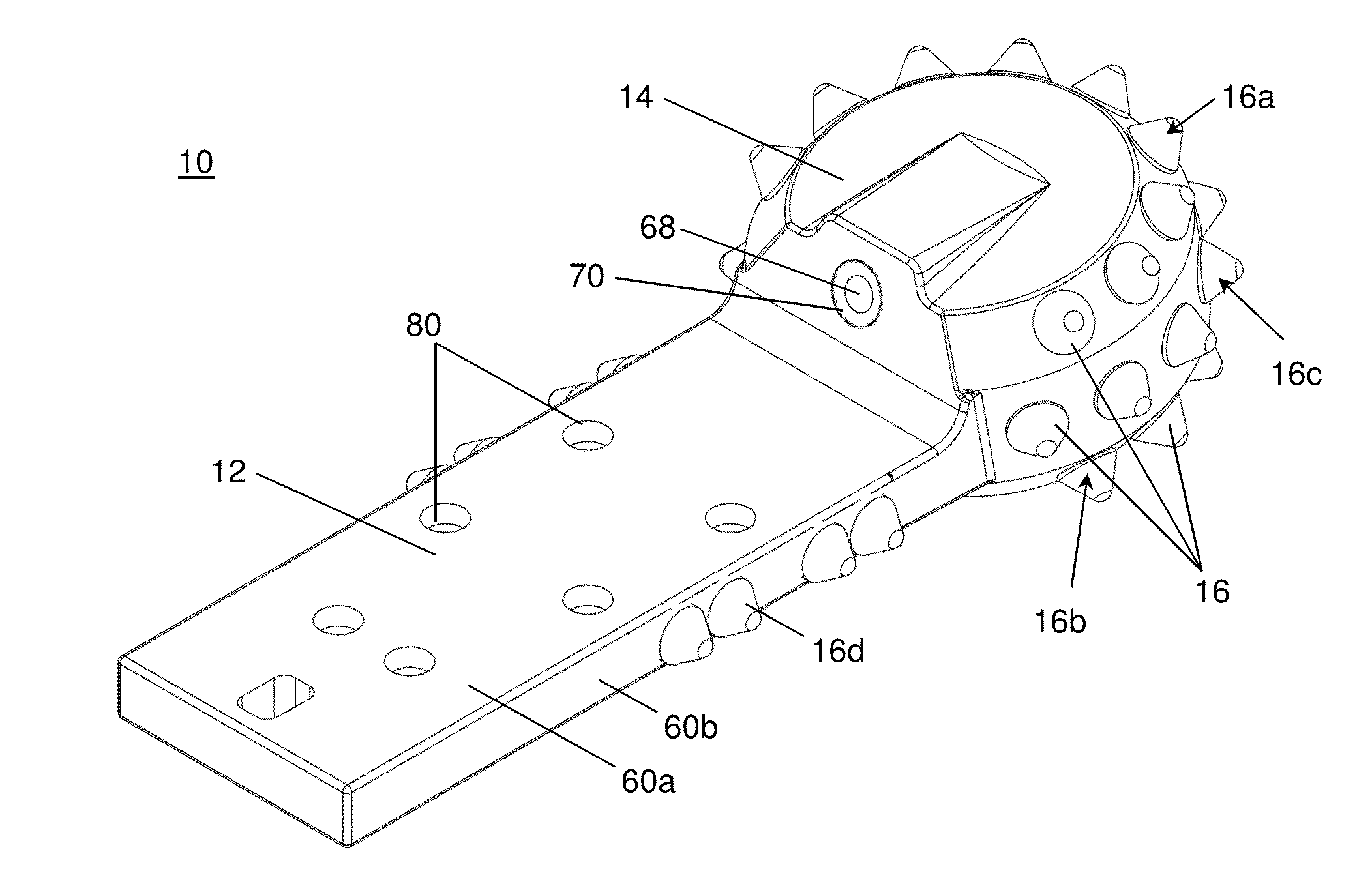
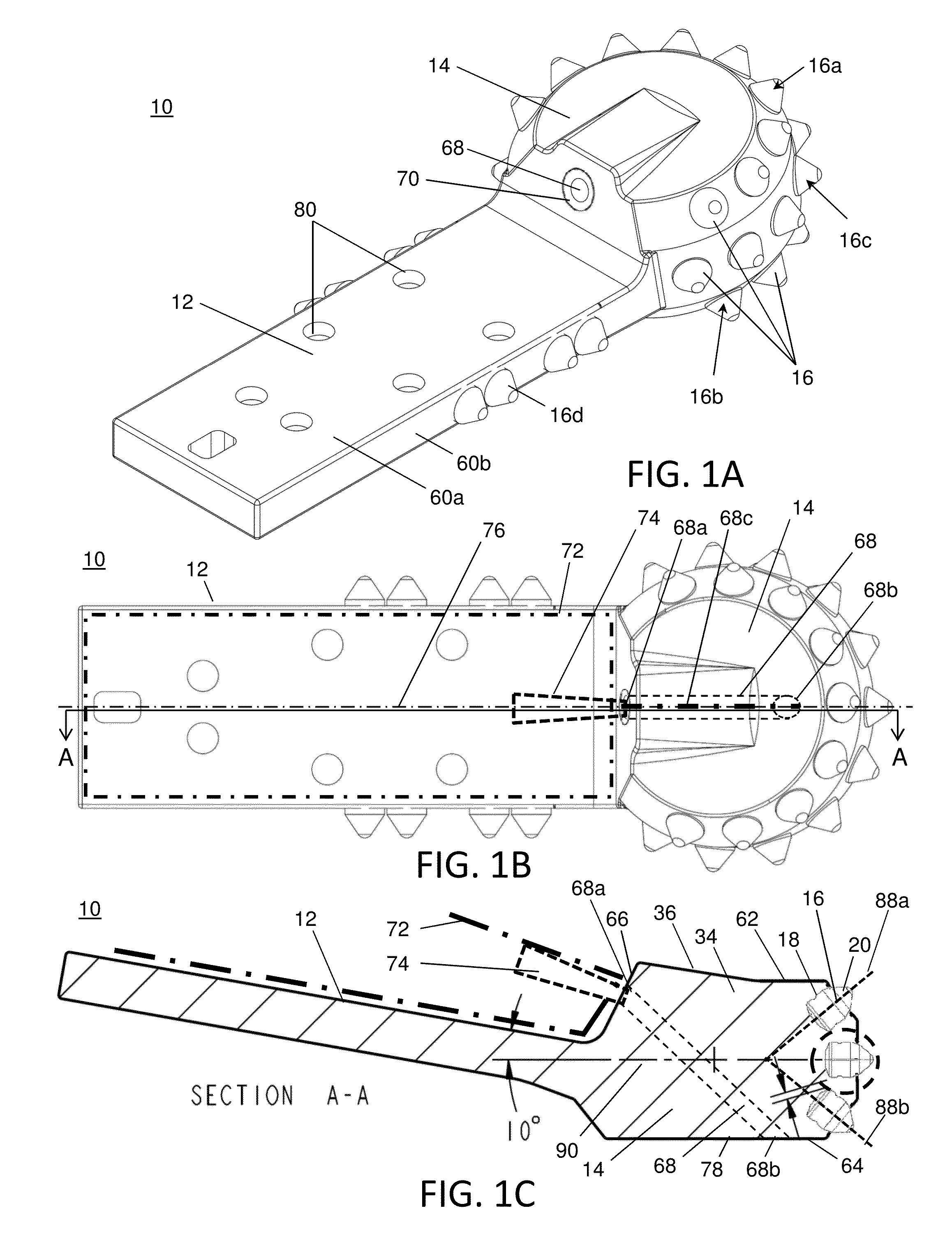
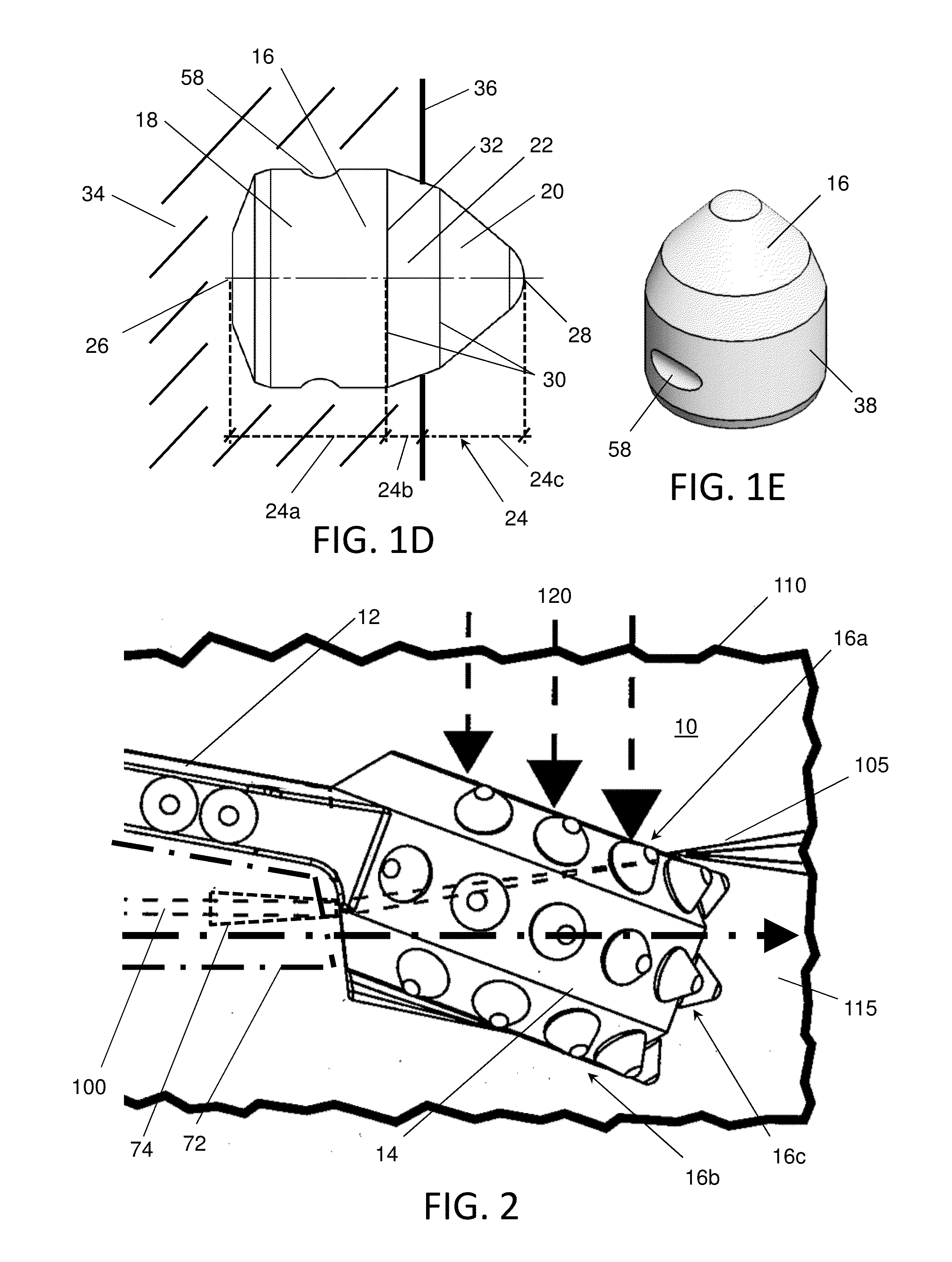
[0023]The following description of the inventive boring bit 10 for a horizontal directional drilling machine is merely exemplary in nature and is in no way intended to limit the invention, its application, or uses. Generally, as shown in FIG. 1A, the boring bit 10 of the present invention has a body with a head portion 12 connected to a shank portion 14, and teeth 16 are radially distributed around the periphery of the head portion. Preferably, the head has an upper row of teeth 16a, a lower row of teeth 16b and a middle row of teeth 16c which are angled relative to each other. In particular, the upper and lower rows have diverging teeth axes 88a, 88b relative to a plane 90 through the center of the head, and the axes of the teeth in the middle row are aligned with the head's center plane. The head has a top surface 62 proximate to the upper row, a bottom surface 64 proximate to the lower row, and angled surface 66 between the shank 14 and the top surface 62. Also, as explained in f...


PUM


Abstract

A boring bit has a shank, a head and teeth distributed around the head. The teeth have a root embedded within the head's core body, a tip extending out of the head, and a narrowing region between the root and the tip. More than approximately two-thirds of the tooth length is embedded in the core body, including a portion of the narrowing region. Stabilizing rods are welded to the tips of the teeth to form a temporary connection, and the core body is formed from a molten metal poured into a cavity of a cast mold. The rods are inserted into indentations in the cast to hold the teeth in place, and the molten metal heats the teeth and weld to substantially loosen the temporary connection. As the molten metal cools, it solidifies around the teeth and secures the root and narrowing region of the teeth within the core body.

Description

CROSS-REFERENCE TO RELATED APPLICATIONS[0001]This application claims priority from U.S. Provisional Patent Application No. 61 / 786,516 filed on Mar. 15, 2013 which is hereby incorporated by reference.STATEMENT REGARDING FEDERALLY SPONSORED RESEARCH[0002]Not Applicable.APPENDIX[0003]Not Applicable.BACKGROUND OF THE INVENTION[0004]1. Field of the Invention[0005]The present invention relates to boring bits for the drilling heads of directional boring machines, and more particularly to the design and method of manufacture of the teeth used in the boring bits.[0006]2. Related Art[0007]Boring bits are used in a number of directional boring machines. Generally, directional boring or horizontal directional drilling (HDD) is a steerable trenchless method of installing pipes, conduits and cables along an underground route that is formed from a drilling rig at one end of the route. There are different types of heads used in the pilot-hole process, and they depend on the geological material.[000...

Claims


Application Information

Patent Timeline
Patent Type & Authority Applications(United States)
IPC IPC(8): E21B10/62B24D18/00
CPCB24D18/0009E21B10/62E21B7/064E21B7/065
Inventor FORD, DOUGLAS R.
Owner ROCKHOUND BORING PROD LLC DBA US DRILLING PROD
Why Eureka
Try Eureka