
Tubular light source having overwind

a light source and tube technology, applied in the field of tube lamps, can solve problems such as the deformation of the lamphead

Inactive Publication Date: 2014-09-18
APPLIED MATERIALS INC
View PDF7 Cites 3 Cited by
  • Summary
  • Abstract
  • Description
  • Claims
  • Application Information

AI Technical Summary

Benefits of technology

The present invention is about a new type of tubular lamp that has a coil filament with an overwrap. This design provides better control over the light output and longer life of the lamp compared to traditional halogen lamps. The ratio of the first diameter to the second diameter of the lamp is important - it affects the light output and the longevity of the lamp. This new design can be used in a variety of applications such as RTP apparatus.

Problems solved by technology

Heat absorbed in the lamphead can also cause the lamphead to deform.

Method used


Image

  • Tubular light source having overwind
  • Tubular light source having overwind
  • Tubular light source having overwind

Examples


Embodiment Construction

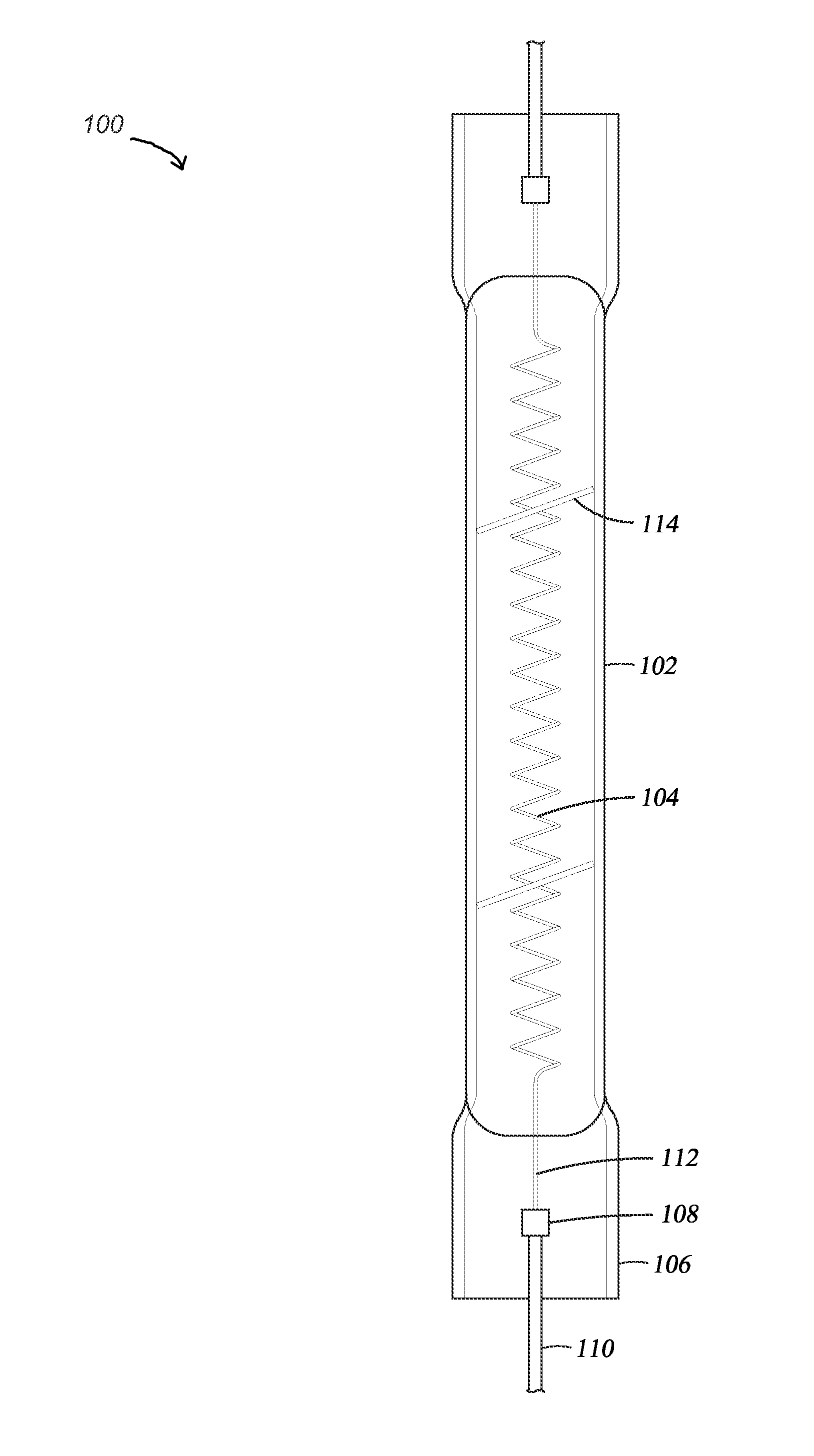
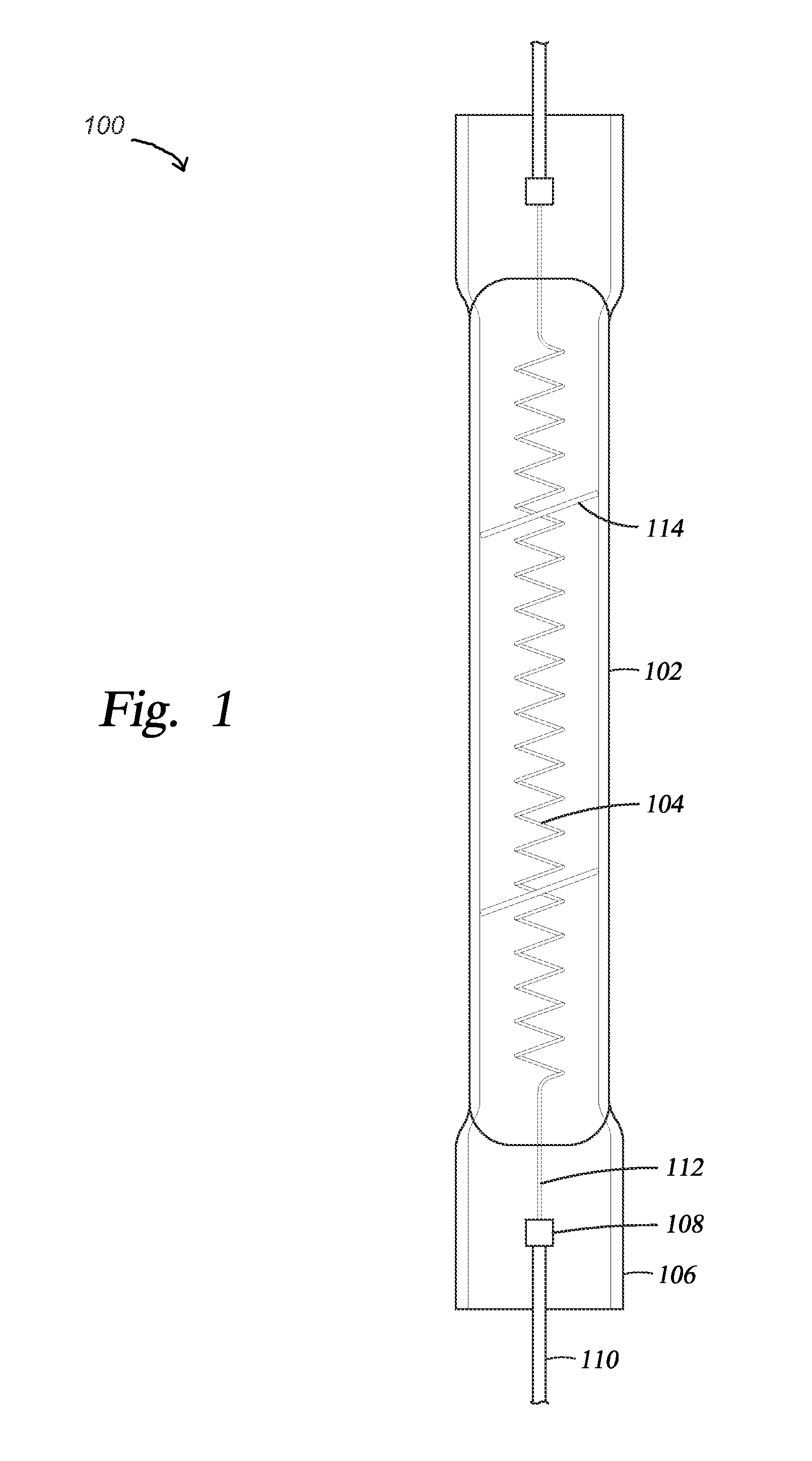
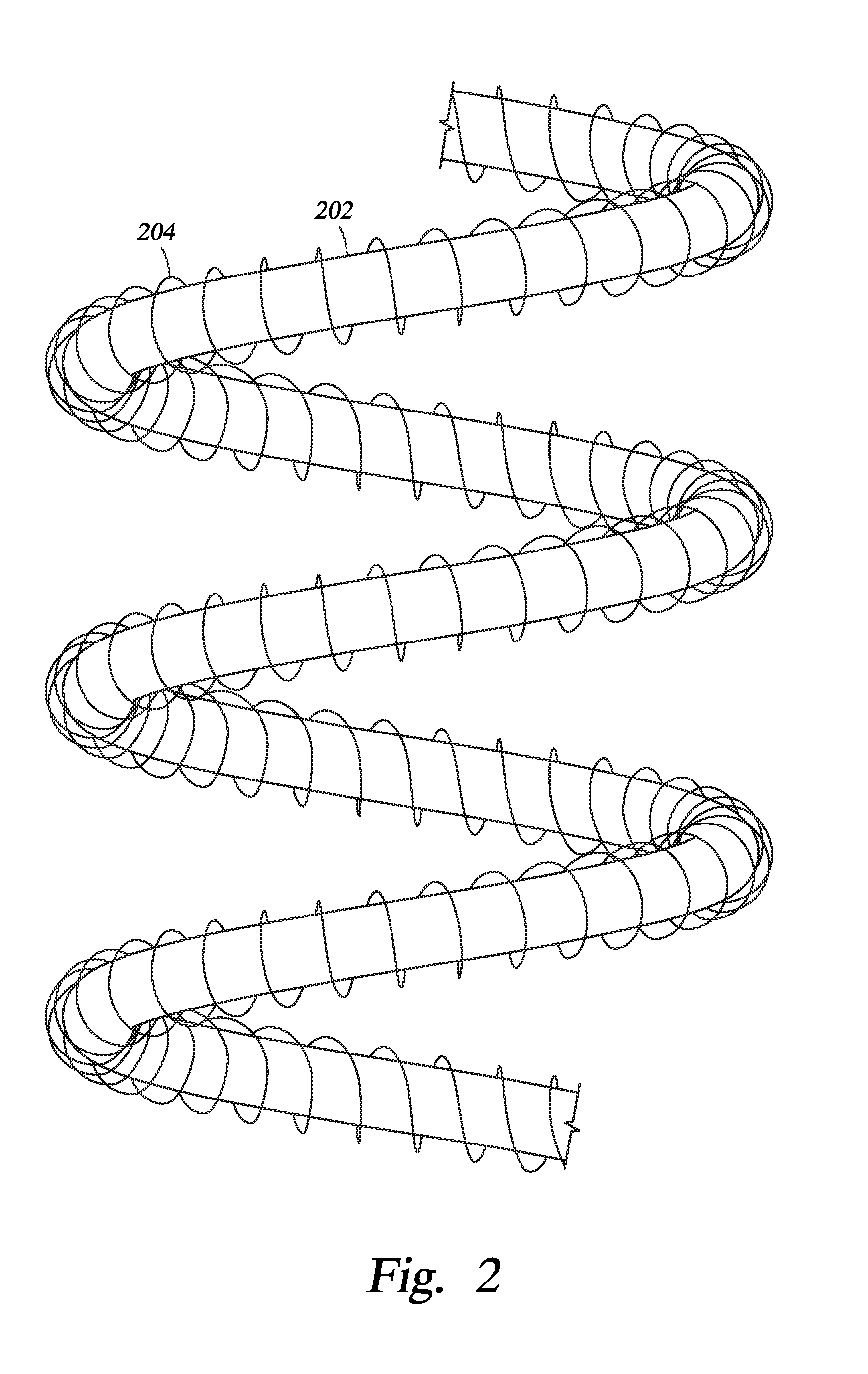
[0020]Embodiments of the present invention generally relate to a tubular lamp with a coil filament having an overwind wrapped around the coil. In one embodiment, the tubular lamp has a coiled coil filament, and the coiled coil has an overwind wrapped around the coiled coil.

[0021]FIG. 1 is a side view of a tubular lamp 100 according to an embodiment of the invention. The tubular lamp 100 may be an incandescent lamp. In one embodiment, the tubular lamp 100 is a halogen lamp. The tubular lamp 100 has a tubular envelope 102 having two ends. Each end is connected to a lamp base 106. The envelope 102 may be made of light-transmissive materials, such as quartz, silica glass, or aluminosilicate glass. The cross section of the tubular envelope 102 may be a circle. The cross section of the tubular envelope 102 may have a non-circular shape, such as square, rectangle, triangle, or polygonal. The envelope 102 may be substantially linear or may take on the form of an arc or series of arcs and st...


PUM


Abstract

Embodiments of the present invention generally relate to a tubular lamp with a coiled filament having an overwind wrapped around the coil. In one embodiment, the tubular lamp has a coiled coil filament, and the coiled coil has an overwind wrapped around the coiled coil.

Description

CROSS-REFERENCE TO RELATED APPLICATIONS[0001]This application claims priority to U.S. Provisional Patent Application Ser. No. 61 / 788,137, filed on Mar. 15, 2013, which herein is incorporated by reference.BACKGROUND[0002]1. Field[0003]Embodiments of the present invention generally relate to a tubular lamp. More particularly, embodiments described herein relate to a tubular lamp for a rapid thermal processing (RTP) apparatus.[0004]2. Description of the Related Art[0005]RTP systems are employed in semiconductor chip fabrication to create, chemically alter, or etch surface structures on semiconductor substrates or wafers. RTP typically depends upon an array of high-intensity incandescent lamps fit into a lamphead and directed at the substrate. The lamps are electrically powered and can be very quickly turned off and on and a substantial fraction of their radiation can be directed to the substrate. As a result, the substrate can be very quickly heated without substantially heating the ch...

Claims


Application Information

Patent Timeline
Patent Type & Authority Applications(United States)
IPC IPC(8): H01K5/02
CPCH01K5/02H01K1/04H01K1/10H01K1/14H01K1/28H05B3/0014H05B3/0047H05B3/12
Inventor RANISH, JOSEPH M.
Owner APPLIED MATERIALS INC
Learn More