
Coil Bioabsorbable Stents

a bioabsorbable, coil technology, applied in the field of coil stents, can solve the problems of reducing the clinical effect of the treatment agent, affecting the quality of the treatment, so as to promote resolution and hemostasis, local variation in stent flexibility and rigidity, and increase flexibility

Active Publication Date: 2013-10-03
MANLI INT
View PDF21 Cites 8 Cited by
  • Summary
  • Abstract
  • Description
  • Claims
  • Application Information

AI Technical Summary

Benefits of technology

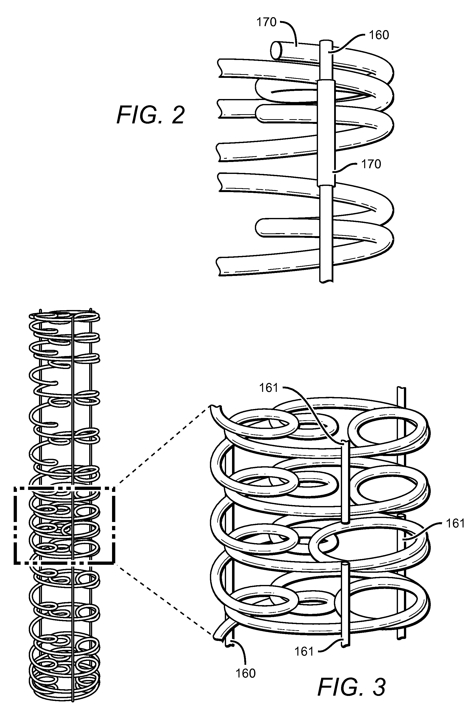
This patent describes a stent design that allows for flexibility and rigidity to be adjusted in different parts of the stent without changing its composition or size. The stent includes longitudinal support rods and can also have breaks between them to provide variable regions of flexibility. This design allows for better outcomes in treating blockages and aneurysms.

Problems solved by technology

However, each of the features creates challenges in the design and manufacture of stents
However, these processes suffer from significant limitations.
First, the temperature at which the polymer can be melted may cause degradation of the therapeutic agent.
However, this limits the amount of bioavailable drug that can be packaged within the stent, and which would be available in vivo for therapeutic use.
While these materials are effective to provide the desired structural strength to the stent, they suffer from the drawback that they have very long degradation time.
This can lead to issues such as foreign body reactions.
It is also difficult to vary the composition of the stent over its length in order to provide variable strength and / or flexibility in different regions of a stent.
As a result, strength and flexibility are generally opposing outcomes of stent design.
However, this technique alters the mechanical properties of the stent, as well as reduces the proportion of the stent that is available for inclusion of the desired therapeutic agent(s).

Method used


Image

  • Coil Bioabsorbable Stents
  • Coil Bioabsorbable Stents
  • Coil Bioabsorbable Stents

Examples


Embodiment Construction

[0022]The present invention is based on the need to provide a bioabsorbable stent that has both high strength and flexibility. The stent also provides additional features and advantages such as variably flexible regions, radio-opacity and drug-elution ability. The stent also provides for being convertible between a furled state and expanded state. The stent in a furled state is mounted on a balloon catheter that is easily delivered to a desired location in vivo. When at the desired location, the stent can be readily unfurled to the expanded state, which provides the intended structure for therapeutic effectiveness.

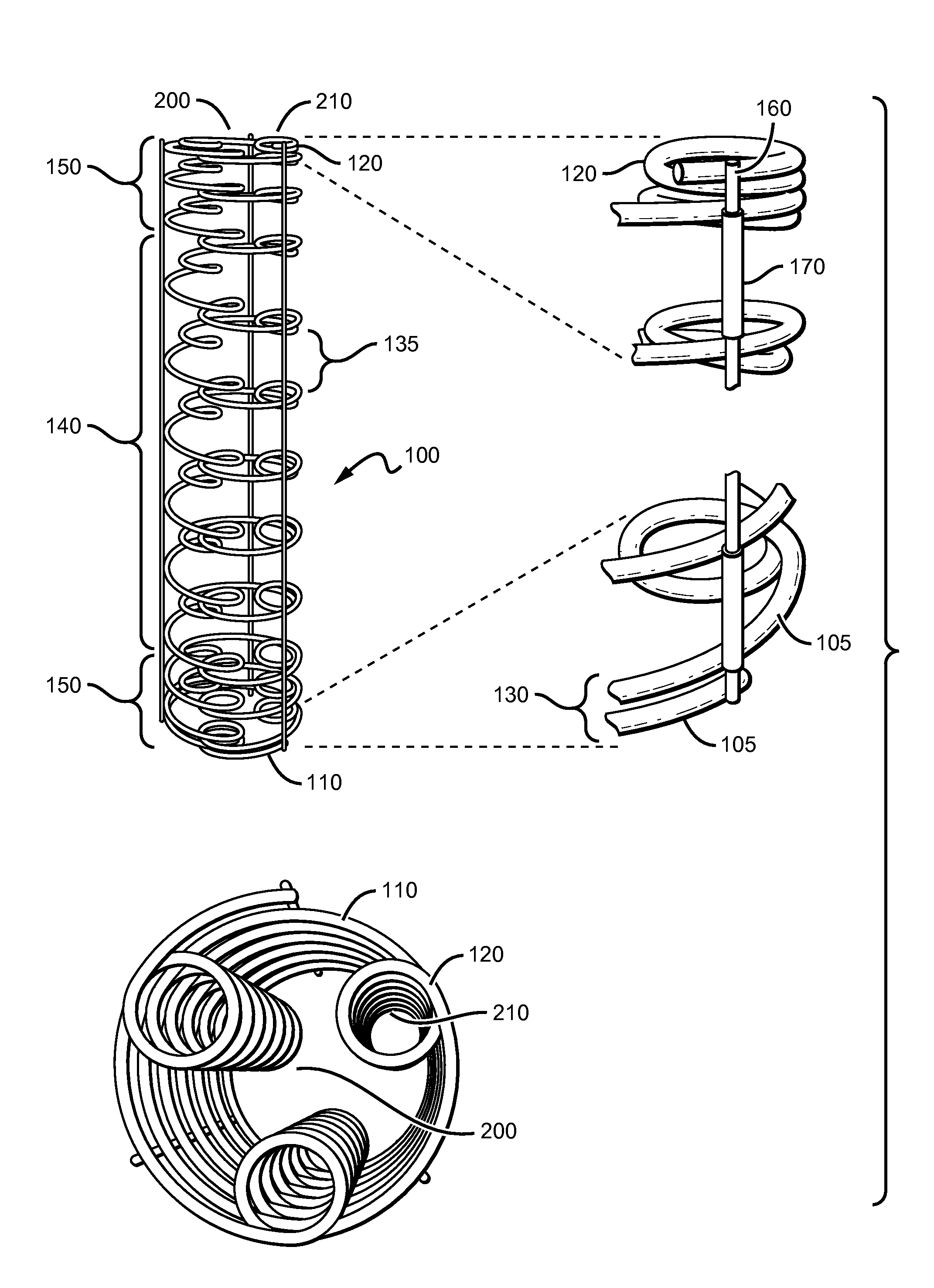
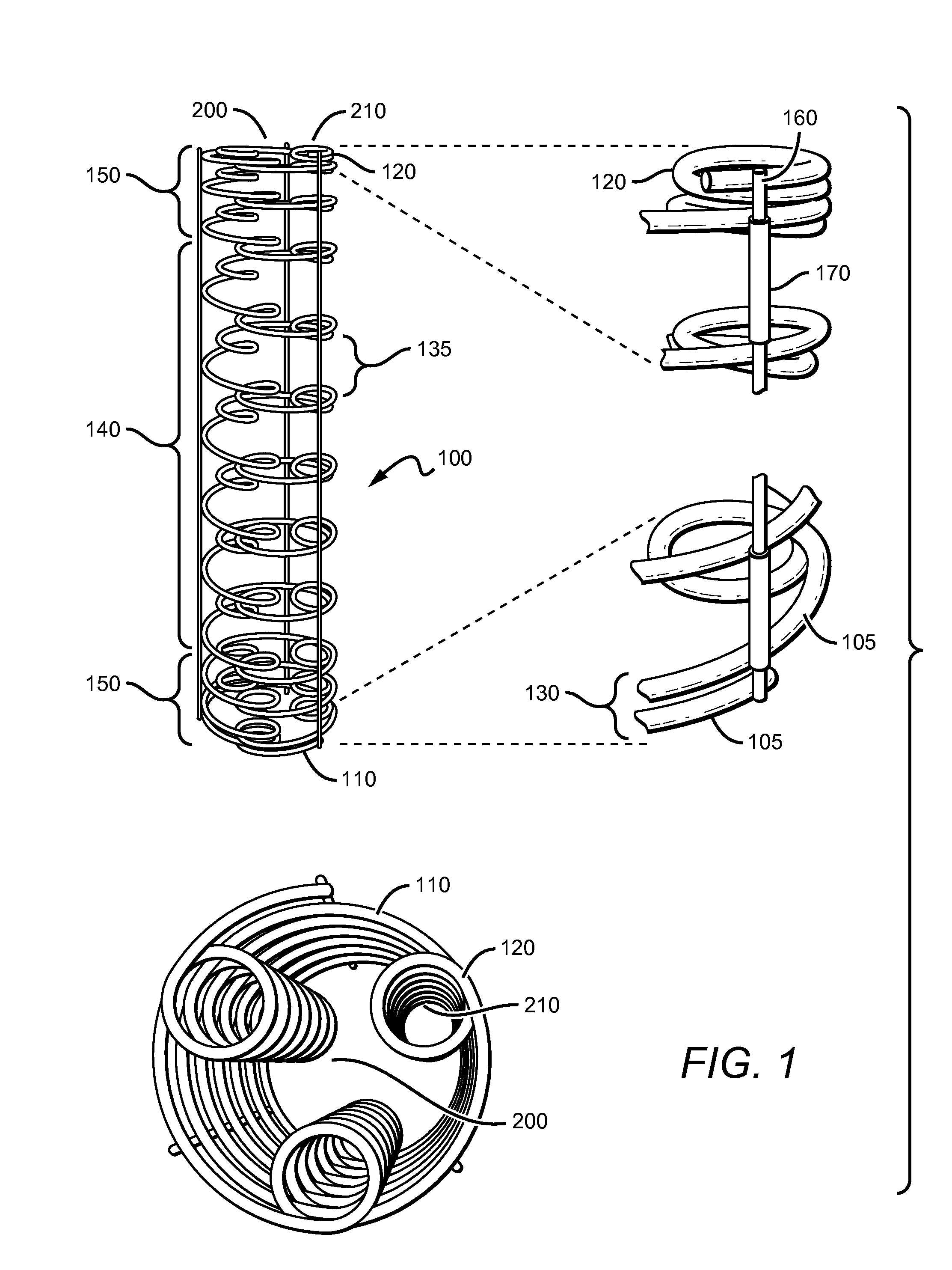
[0023]As can be seen in FIG. 1, the stent 100 generally comprises a coiled-coil structure formed by differentially curving a substantially continuous primary fiber or fibers 105 along the fiber length. Primary coils having the larger radius 110 are oriented around a major longitudinal axis 200, while secondary coils 120 are oriented around one or more lateral longitudinal ...


PUM

PropertyMeasurementUnit
Lengthaaaaaaaaaa
Angleaaaaaaaaaa
Diameteraaaaaaaaaa

Abstract

An expandable, bioabsorbable stent having a coiled-coil configuration is described. The stent further comprises regions of variable pitch that allow for variation in either rigidity, or variability diameter within sub-regions along the length of the deployed stent. By varying the diameter allows the stent to extend into regions such as branched vessels, or into the neck of aneurysms. In some embodiments, the stent comprises longitudinal support fibers that run substantially the length of the deployed stent to provide additional strength. In addition, the stent may also comprise regional support fibers that run less than the length of the stent, and which provide increased regional strength while permitting flexibility of the stent. The stent further comprises micro-tubes that are configured to be visible using medical imaging techniques. The stent can be manufactured from materials that are bioabsorbable and / or include the ability to release pharmacologically active substances over time.

Description

PRIORITY CLAIM[0001]This application claims the benefit of priority to and is a continuation-in-part of U.S. patent application Ser. No. 13 / 435,487, filed Mar. 30, 2012 and U.S. patent application Ser. No. 13 / 476,336, filed May 21, 2012, both of which are incorporated by reference in their entireties.FIELD OF THE INVENTION[0002]The field of the invention is related to stents for placement in blood vessels, glands, ducts or organs, and in particular stents that are designed to provide local delivery of therapeutic agents, are bioabsorbable and which can treat occluded or weakened lesions.BACKGROUND[0003]Stents are commonly used as a means of supporting weakened sections of blood vessels, glands or ducts, to re-open lumens of collapsed or occluded vessels, glands or ducts, or as means for treating aneurysms and other diseases. Stents have also been useful as a means of delivering therapeutic agents to specific sites within the vascular or ductal structures of organs. Stents may also b...

Claims


Application Information

Patent Timeline
IPC IPC(8): A61F2/82
CPCA61F2/88A61F2250/0067A61F2210/0004A61F2002/825A61F2250/0098A61F2/885A61F2/954A61F2002/061A61F2230/0067A61F2230/0091A61F2250/0029A61F2250/0039
Inventor SU, SHIH-HORNG
Owner MANLI INT
Learn More