Motor control system having bandwith compensation

a control system and bandwith compensation technology, applied in the direction of motor/generator/converter stopper, motor/electric converter control, transportation and packaging, etc., can solve the problem that the effect of torque ripple compensation at relatively high motor velocities may be diminished

Active Publication Date: 2014-09-18
STEERING SOLUTIONS IP HLDG
View PDF3 Cites 27 Cited by
  • Summary
  • Abstract
  • Description
  • Claims
  • Application Information

AI Technical Summary

Benefits of technology

[0004]In one embodiment, a motor control system for determining a ripple compensating current is provided. The motor control system includes a motor having a plurality of motor harmonics and a motor frequency, and a bandwidth compensation controller that is in communication with the motor. The bandwidth compensation controller is configured to determine a magnitude response comp...

Problems solved by technology

Interior permanent magnet synchronous motors (IPMSMs) are relatively inexpensive, but typically produce a relatively high torq...

Method used


Image

  • Motor control system having bandwith compensation
  • Motor control system having bandwith compensation
  • Motor control system having bandwith compensation

Examples


Embodiment Construction

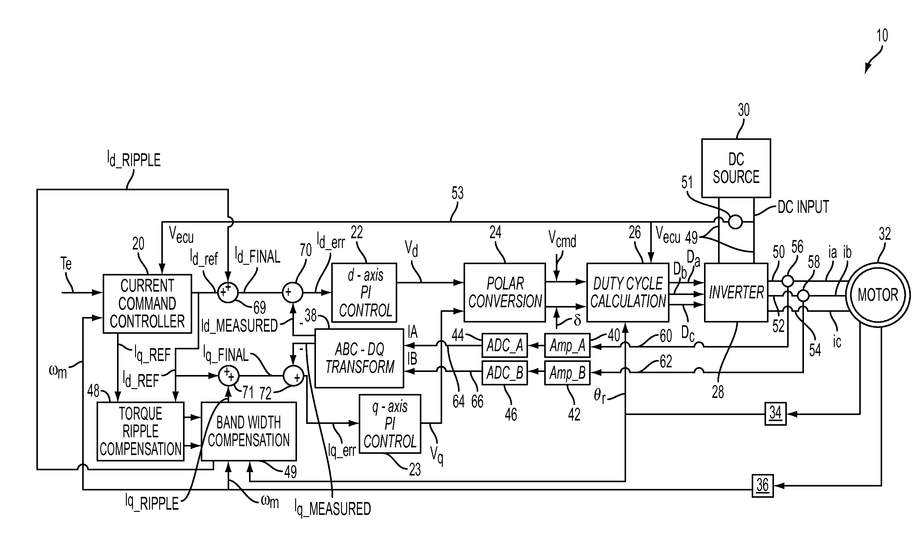
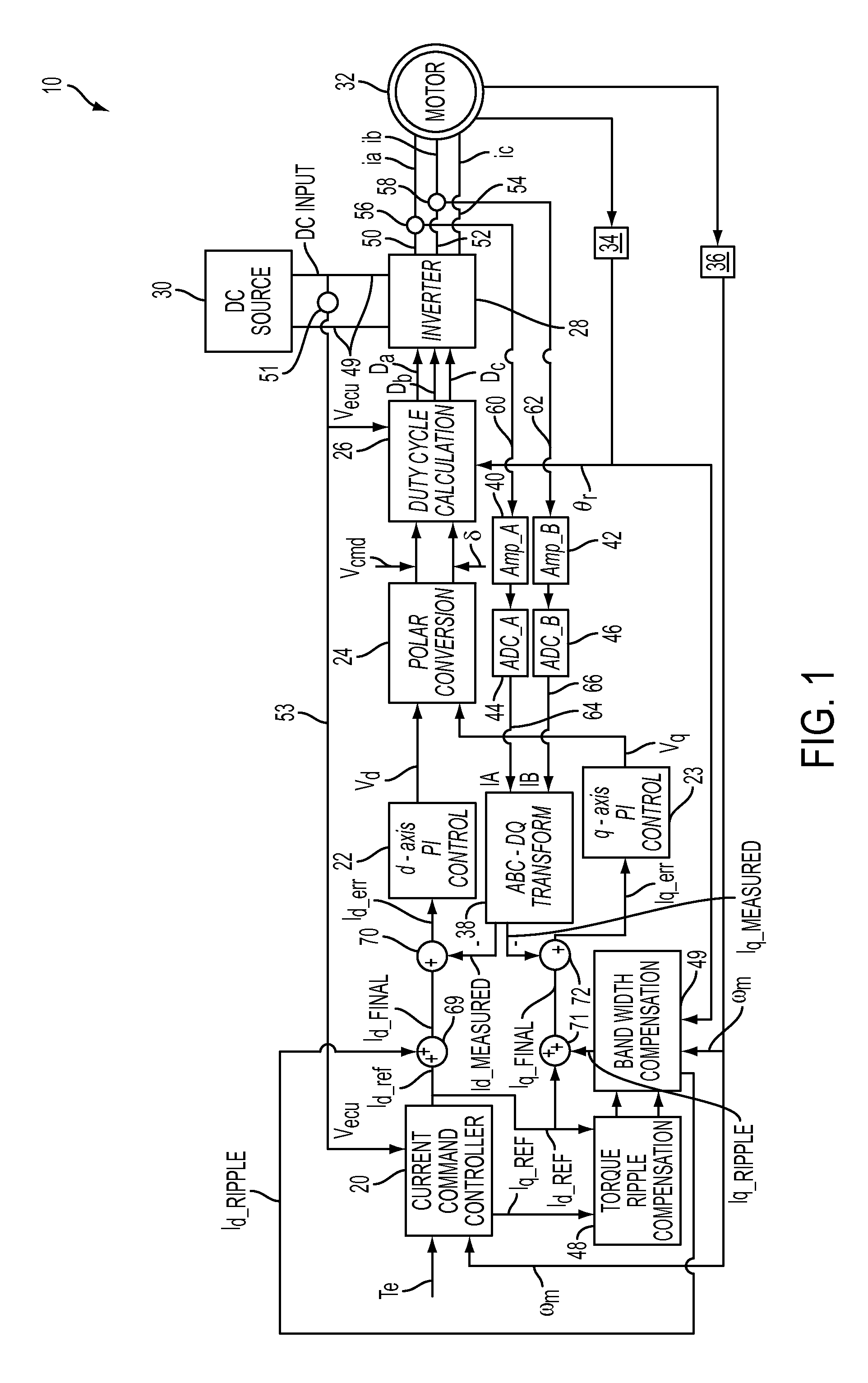
[0011]Referring now to the Figures, where the invention will be described with reference to specific embodiments, without limiting same, FIG. 1 is an exemplary block diagram of a motor control system 10. The motor control system 10 includes a command current controller 20, a d-axis proportional plus integral gain (PI) controller 22, a q-axis PI controller 23, a polar conversion controller 24, a pulse width modulation (PWM) inverter controller 26, an inverter 28, a DC power source 30, a motor 32, a position sensor 34, a speed sensor 36, a transform controller 38, an a-axis current amplifier 40, a b-axis current amplifier 42, an a-axis analog to digital converter (ADC) 44, a b-axis ADC 46, a torque ripple compensation controller 48, and a bandwidth compensation controller 49. In one embodiment, the motor 32 may be an interior permanent magnet synchronous motor (IPMSM) or a surface permanent magnet synchronous motor (SPM), however it is to be understood that any type of electric motor ...


PUM


Abstract

A motor control system for determining a ripple compensating current is provided. The motor control system includes a motor having a plurality of motor harmonics and a motor frequency, and a bandwidth compensation controller that is in communication with the motor. The bandwidth compensation controller is configured to determine a magnitude response compensation value and a phase compensation value for each of the plurality of motor harmonics. The magnitude response compensation value and the phase compensation value are both based on the motor frequency. The bandwidth compensation controller is configured to determine the ripple compensating current based on the magnitude response compensation value and the phase compensation value.

Description

BACKGROUND OF THE INVENTION[0001]The present invention relates to a control system for a motor, and more particularly to a control system for a motor that determines a ripple compensating current.[0002]The output torque of a permanent magnet synchronous motor (PMSM) (either a surface permanent magnet (SPM) or an interior permanent magnet (IPM) motor) may be determined by a voltage command and a phase advance angle. A specific output torque of the PMSM is determined by first selecting a specific quadrature axis (also referred to as the q-axis) reference current and a direct axis (also referred to as the d-axis) reference current, and then determining the voltage command and the phase advance angle based on the selected quadrature axis reference current and the direct axis reference current.[0003]Interior permanent magnet synchronous motors (IPMSMs) are relatively inexpensive, but typically produce a relatively high torque ripple during operation. Electric motors utilized in electric ...

Claims


Application Information

Patent Timeline
IPC IPC(8): H02P31/00
CPCH02P31/00H02P6/10H02P21/05B62D5/046H02P21/22H02P29/50
Inventor GEBREGERGIS, ABRAHAMRAJAVENKITASUBRAMONY, RAMAKRISHNANSEBASTIAN, TOMYPOPY, NIHARIKA P.
Owner STEERING SOLUTIONS IP HLDG
Why Eureka
Try Eureka