Variable Sound Attenuator

a variable and sound technology, applied in the field of ear wear attenuators, can solve the problems of affecting the sound protection of the ear, affecting the hearing of workers, and affecting the work environment, so as to quickly adjust the amount of sound protection, the level of attenuation can be changed, and the communication is not impeded.

Active Publication Date: 2014-09-18
BAUMAN NATAN +1
View PDF4 Cites 11 Cited by
  • Summary
  • Abstract
  • Description
  • Claims
  • Application Information

AI Technical Summary

Benefits of technology

[0022]Accordingly, it is an object of the invention to provide an attenuator that allows for in situ and instantaneous changes of the level of attenuation for those who are in need of ear protection. It is another object of the invention to provide a device that allows the level of attenuation to be changed, so as not to impede communication. It is another object of the invention to provide a device where the user can adjust the amount of attenuation in a variable, continuous fashion from zero attenuation to maximum attenuation. Such change may be made by the user without removing the device from the ear.
[0023]Other objects of the invention allow a user to quickly adjust the amount of sound protection and according to the amount of noise in the environment and also according to the need of being able to maintain communication. Other objects of the invention allow for a variable control attenuation device that is easy to use and that allows a user to control the level of attenuation of the device.

Problems solved by technology

Thousands of workers every year suffer from preventable hearing loss due to high workplace noise levels.
Elevated noise levels at workplace or other noise can cause hearing impairment, hypertension, ischemic heart disease, annoyance, and sleep disturbance.
Noise exposure also has been known to induce tinnitus, hypertension, vasoconstriction, and other cardiovascular adverse effects.
A problem exists whereby there is a need to provide an ear attenuator which allows a user to change the amount of sound protection quickly and according to the amount of noise in the environment and also according to the need of being able to maintain communication.
This is especially true for many older workers, who already have noise-induced hearing loss.
Making hearing protection devices compulsory puts some workers in danger.
In fact, many workers find ways to sabotage hearing protection in order to communicate.”
One consequence of improper attenuation in hearing protection device (HPD) is that a user may reject the hearing protection (as cited above) if it compromises his / her hearing to the extent that sounds no longer appear natural, signals cannot be detected or localized, and / or speech is not intelligible.
In some cases, too much attenuation may be provided by an HPD for a particular noise environment such that the user's hearing is unnecessarily compromised.
The safety professional often faces a dilemma in selecting HPDs for the workforce.
The safety officer faces a dilemma of under protection versus overprotection.
They do not allow for any variability of the attenuation level.
However, this device does not allow for a transparency of the incoming speech sounds or other warning sounds when needed.
Furthermore, the SonoCustom™ is not a functional / practical system where the user can quickly adjust the attenuation level as desired.
Again, the practically of such device is questionable and in its least attenuation mode it still impairs user's detection of important sounds.
This device, therefore, is preset and does not allow the user to select his / her own attenuation level
Again, the Combat Arms ear plug does not allow the user to vary level of sound attenuation as desired.
In U.S. Pat. No. 8,550,206 to Keady et al. involves hearing protection devices capable of tunable acoustic attenuation; “The invention relates further to ear plugs comprising a fluid-containing balloon for occlusion of the ear canal, which are capable of being adjusted for example by modifying fluid composition and / or fluid pressure within the balloon to vary attenuation at different frequencies of the audible sound spectrum.” One objection to such a device is that it is difficult to confine the fluid reservoir and another disadvantage is that the fluid body itself can act as a fairly good conductor of sound and thereby defeats to some degree the purpose of the attenuation device.
Another foreseeable problem is that the inflated pressure may alter in the ear canal cavity over time as the device will move with time due to balloon flexibility.
This may result in fluctuating changes in the attenuation level.

Method used


Image

  • Variable Sound Attenuator
  • Variable Sound Attenuator
  • Variable Sound Attenuator

Examples


Embodiment Construction

[0074]U.S. Provisional No. 61 / 790,243, entitled “Variable Noise Attenuator” and filed on Mar. 15, 2013 is herein incorporated into this application in its entirety.

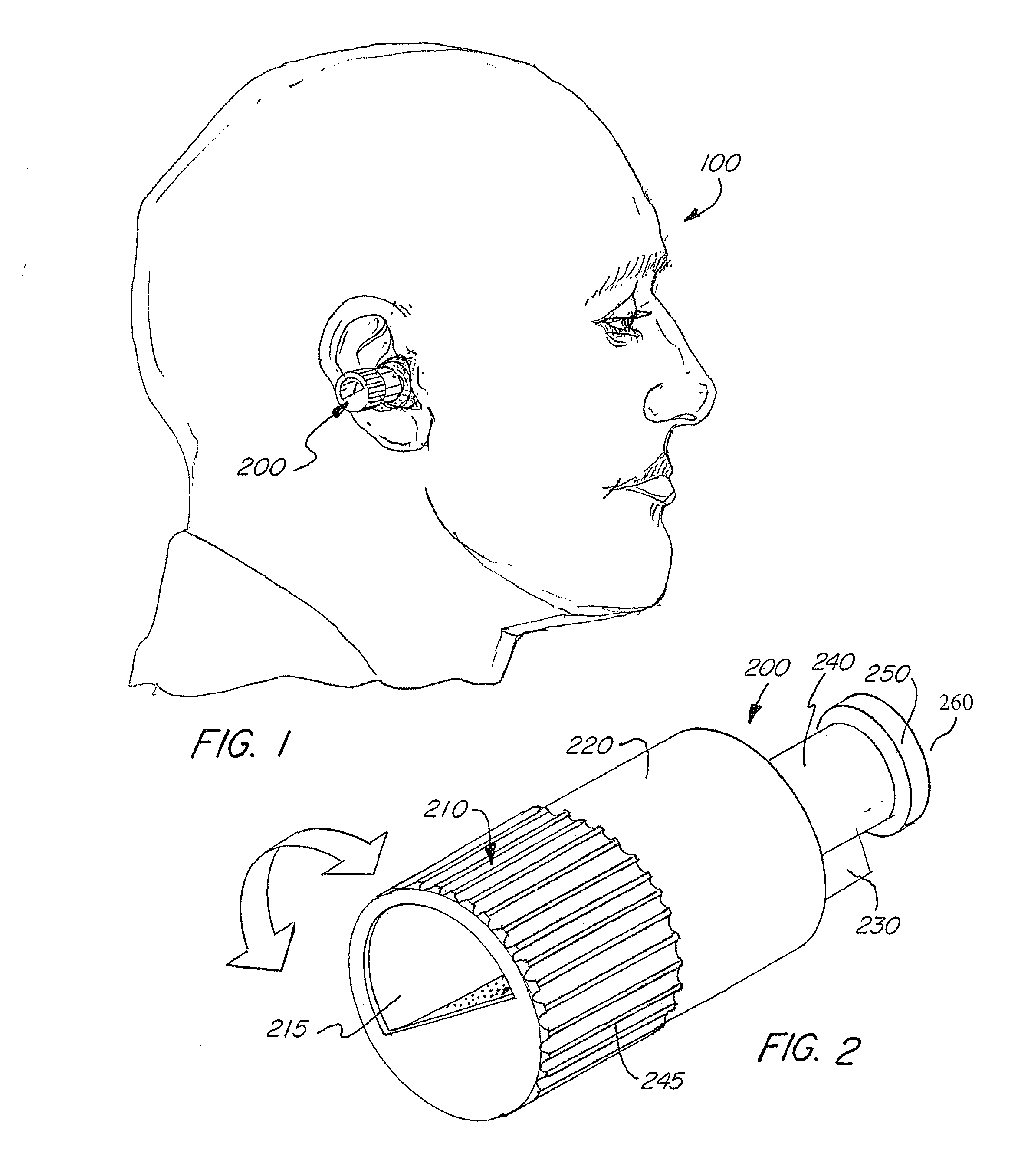
[0075]Referring to FIG. 1, a VSA also referred to as an attenuator 200, is shown within the ear of a user 100. The attenuator 200 is shown in additional detail in FIG. 2.

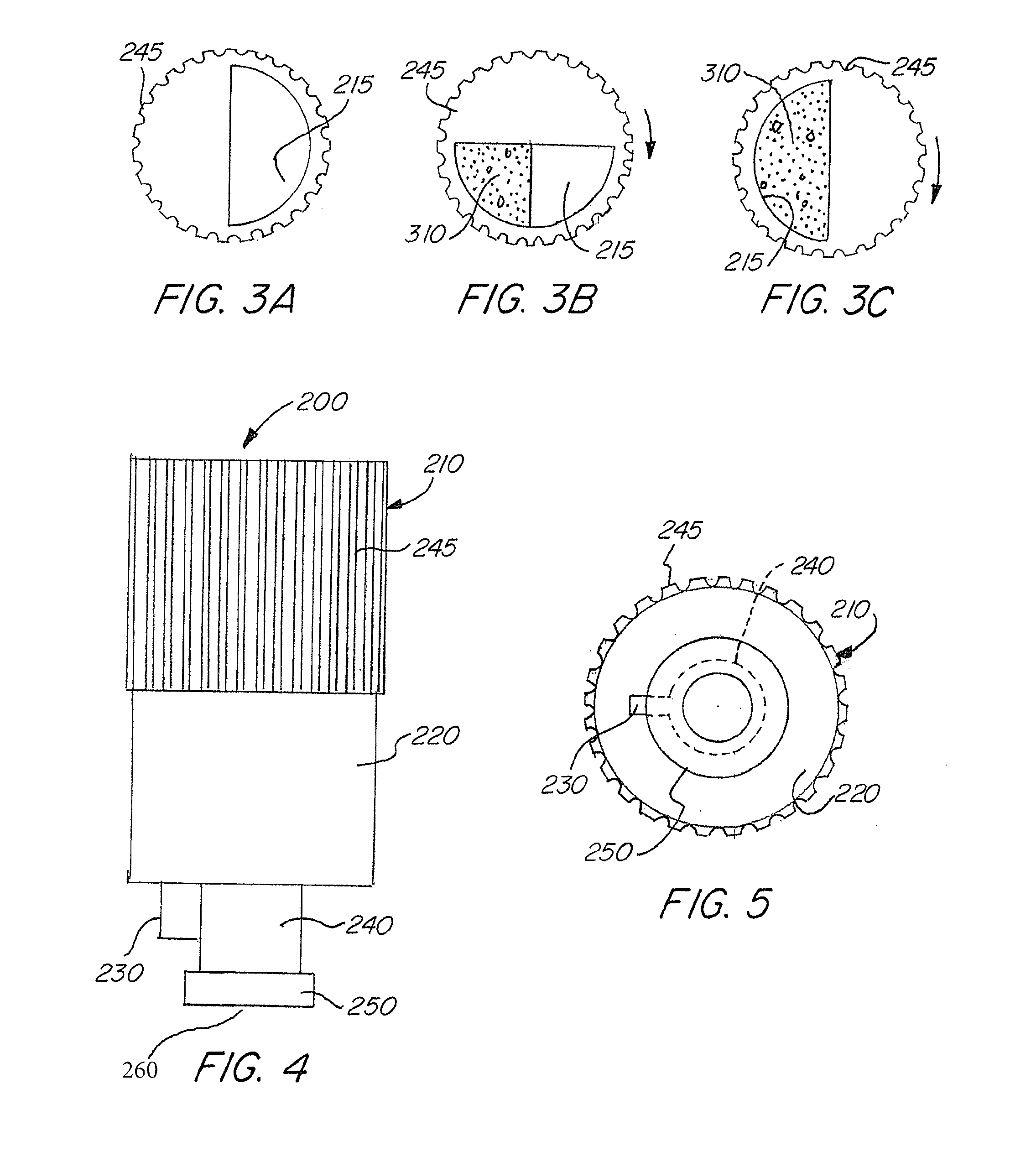
[0076]Referring to FIG. 2, the exterior design of an attenuator 200 of an embodiment of the invention is shown. Here, the attenuator 200 is shown having an upper vented opening 215, a top housing 210 with ribs 245, a bottom housing 220, a locking fin 230 that prevents twisting, a narrow extension 240 and a nub 250 for retention in an earpiece. The nub 250 has a bottom vented opening 260 passing through the nub 250. The top housing 210 is able to rotate radially with regards to bottom housing 220, via rotation of the top housing 210 on the bottom housing 220 in the direction of the arrow. The top housing 210 and the bottom housing 220 are shown having subs...


PUM


Abstract

A sound attenuator that allows a user to adjust the amount of attenuation in a variable, continuous fashion or in a discrete controlled fashion from zero attenuation to maximum attenuation without removing the device from the ear. The ear attenuator includes a housing having a passageway, the passageway allowing for sound to pass through the housing and a variable control, the variable control able to control the size of the passageway through the housing and the amount of attenuating material located within the passageway through the housing.

Description

FIELD OF THE INVENTION[0001]An ear worn attenuator that allows a user to adjust the amount of sound attenuation in a variable, continuous and or discrete fashion from zero attenuation to maximum attenuation without removing the device from the ear.BACKGROUND OF THE INVENTION[0002]According to Occupational Safety & Health Administration (OSHA), about 30 million people in the United States are exposed to hazardous occupational noise every year (Internet, United State Department of Labor, OSHA, Safety and Health Topics, 2014). Noise-related hearing loss has been listed as one of the most widespread occupational health concerns in the United States for more than 25 years. Thousands of workers every year suffer from preventable hearing loss due to high workplace noise levels. Rosenhall U, Pedersen K, Svanborg A (1990). “Presbycusis and noise-induced hearing loss”. Ear Hear 11 (4): 257-63; Schmid, R E (2007 Feb. 18). “Aging nation faces growing hearing loss”. CBS News. Retrieved 2007 Feb....

Claims


Application Information

Patent Timeline
Patent Type & Authority Applications(United States)
IPC IPC(8): H03G3/02
CPCH03G3/02A61F11/08G10K11/175A61F11/085H03G3/04
Inventor BAUMAN, NATANCAMPAGNA, RALPH T.
Owner BAUMAN NATAN
Why Eureka
Try Eureka