Shutter blade and robot blade with cte compensation

a robot blade and cte compensation technology, applied in the direction of vacuum evaporation coating, manufacturing tools, arms, etc., can solve the problems of reducing the usable life of the heater, and affecting the operation of the heater

Active Publication Date: 2014-09-18
APPLIED MATERIALS INC
View PDF7 Cites 164 Cited by
  • Summary
  • Abstract
  • Description
  • Claims
  • Application Information

AI Technical Summary

Problems solved by technology

The titanium nitride layer is typically brittle and may flake off during subsequent processes.
However, the temperature of the blade varies as different process steps are performed and, as a result, the position of the shutter disk is shifted due to the effects of uncoordinated lifting and lowering of the shutter disk on the robot arm with respect to the temperature change.
Even when using a low CTE (coefficient of thermal expansion) blade material, the variation in shutter disk radial displacement can be significant so as to expose the heater which the shutter disk is intended to protect to unplanned deposition and damage which may require additional positioning cycles to correct and / or repair, each of which reduces the usable life of the heater.
A misalignment between the shutter disk and the robotic arm may result in a portion of the shutter disk remaining in the path of the ceramic substrate support (heater).
As the ceramic support is elevated into a process position, a portion of the substrate may contact the shutter disk, which may result in damage to the substrate or misalignment of the substrate on the ceramic support.
Moreover, if the shutter disk comes in contact with the ceramic support, the ceramic support may become chipped or damaged and necessitate replacement.
Additionally, if the shutter disk is not properly aligned on the robotic arm, the disk may be misaligned relative to the ceramic support (heater) during the burn-in and pasting process, thereby resulting in unwanted deposition on a portion of the ceramic support.
Deposition material on the ceramic support may lead to particle generation, scratching of the wafer and a deterioration of process performance.

Method used


Image

  • Shutter blade and robot blade with cte compensation
  • Shutter blade and robot blade with cte compensation
  • Shutter blade and robot blade with cte compensation

Examples


Embodiment Construction

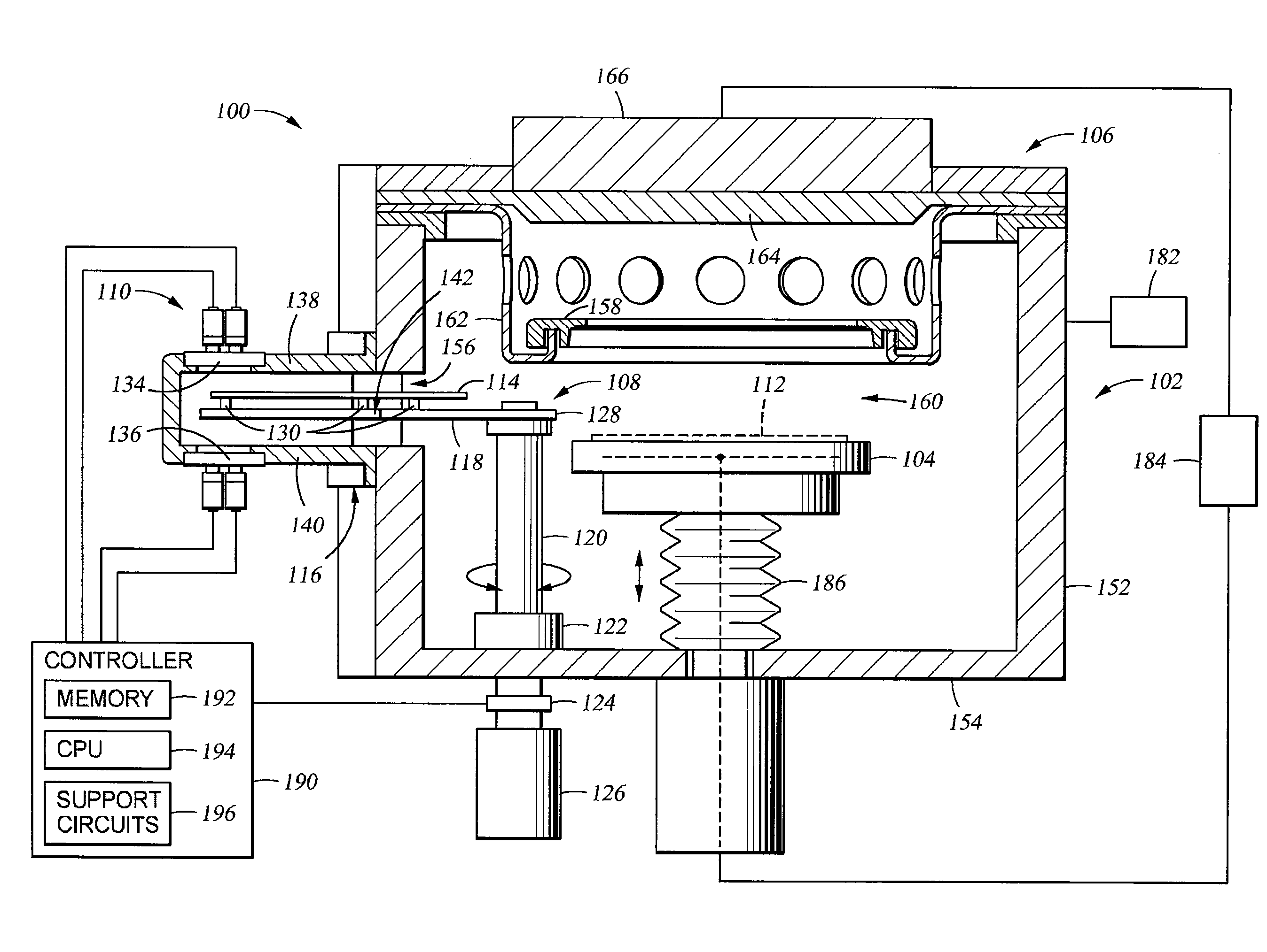
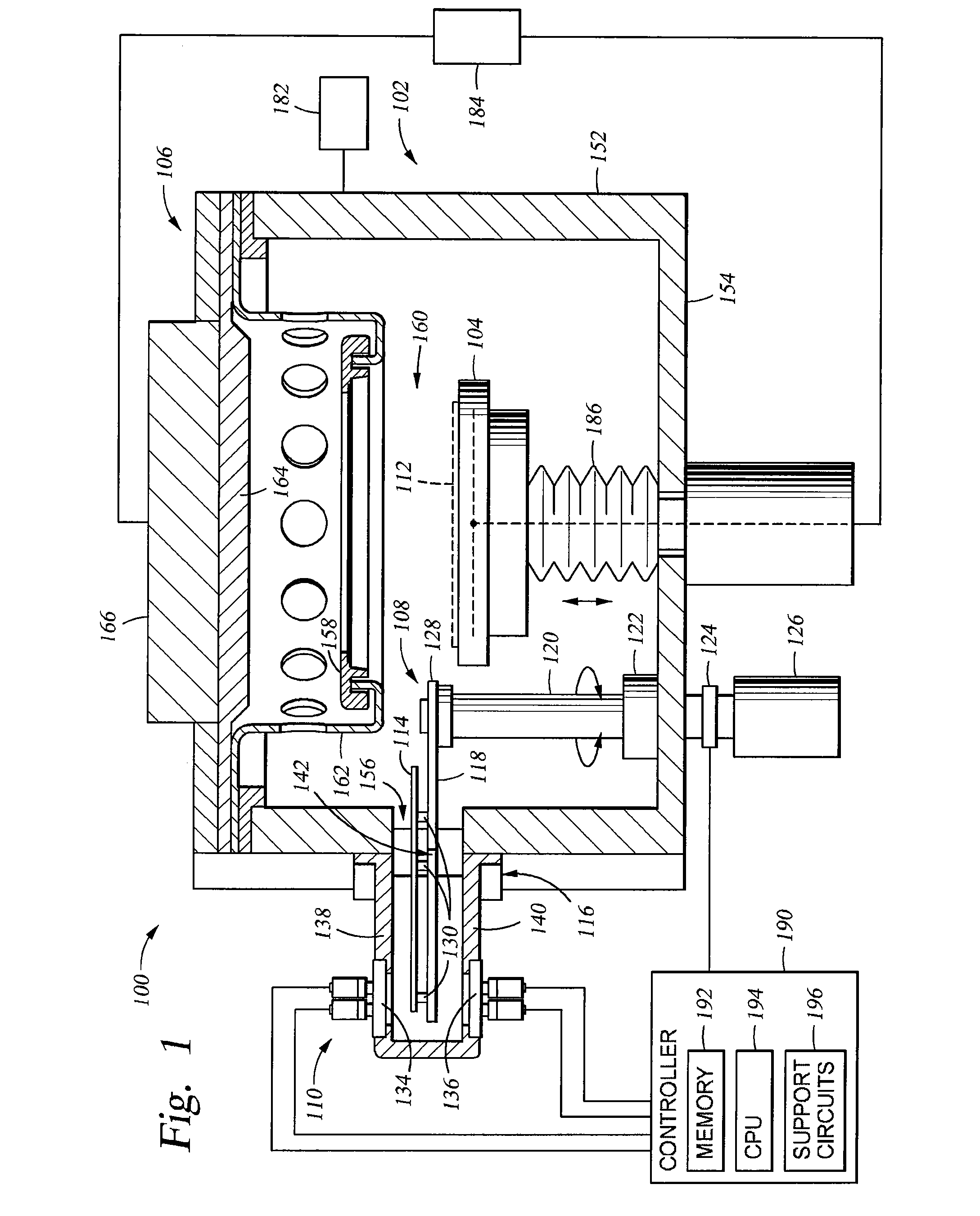
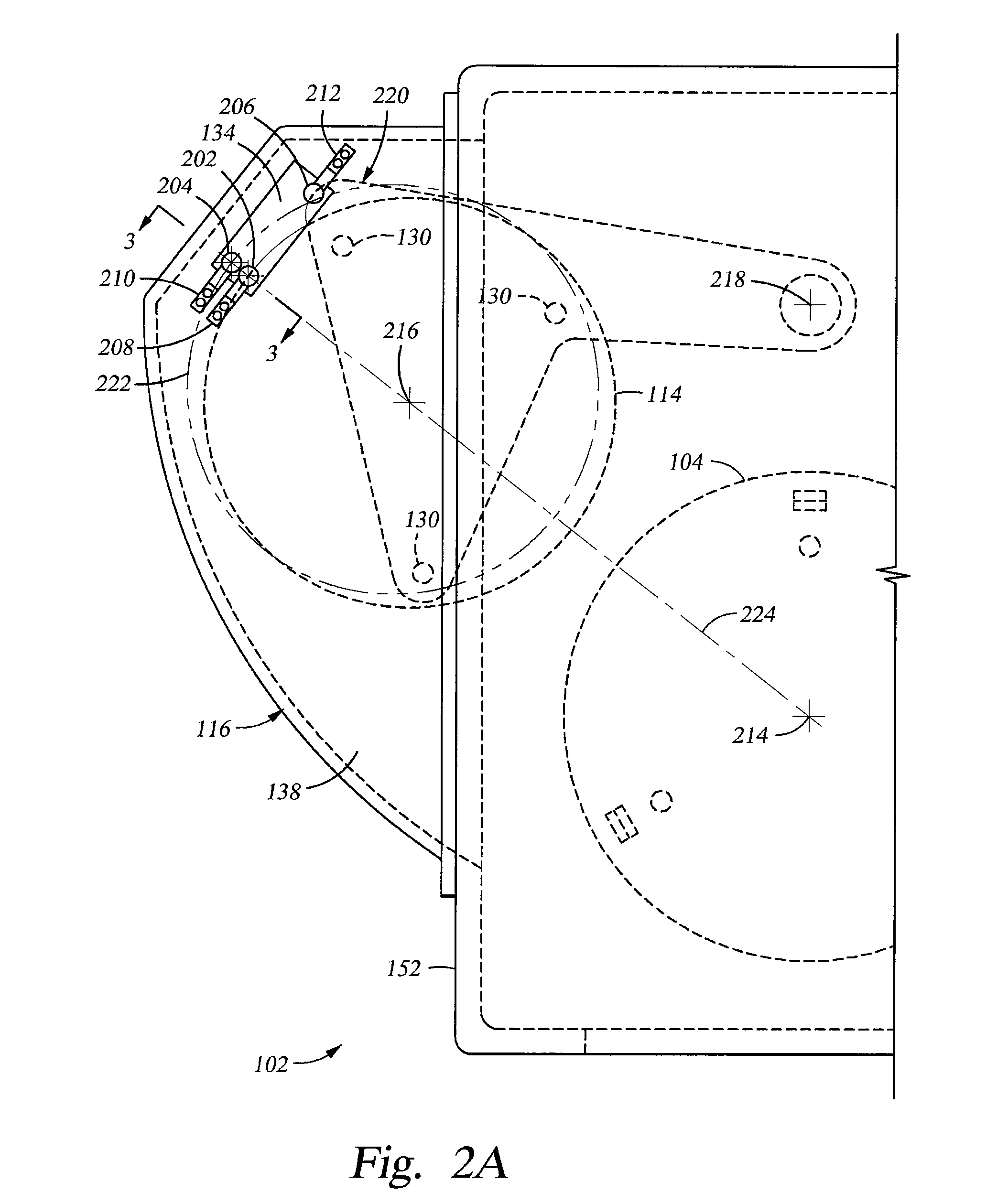
[0040]Embodiments of the disclosure generally provide one or more deposition conditioning assemblies that are adapted to prevent deposition of a material on critical components within a processing chamber during one or more conditioning operations, such as a burn-in or pasting processes. In some configurations, the deposition conditioning assemblies may include a utility wafer that is used to protect the critical components found within the processing chamber. In some embodiments, a semiconductor processing system having a sensor assembly adapted to detect a cleared position of the utility wafer, such as a shutter disk is generally described herein. The “cleared position” is generally defined as a position where a substrate support (and substrate seated thereon) may move vertically without contacting the shutter disk or mechanisms associated with the movement of the shutter disk. Although the embodiments are described in a physical vapor deposition chamber, the disclosure is one of ...


PUM

PropertyMeasurementUnit
CTEaaaaaaaaaa
distanceaaaaaaaaaa
thermal compensatingaaaaaaaaaa

Abstract

Processing chamber shutter blade and robot blade assemblies are constructed to eliminate thermal effects on the placement of elements in processing chambers. Such blade assemblies may contain at least two parts, which may include a positioning member including a low CTE material and a thermal compensating member including a high CTE material. The positioning member includes a coupling point and a reference point on a reference axis separated by a first distance. The thermal compensating member includes a connection point and a controlled point separated by another distance that is less than the first distance. A distance ratio of the first distance to the other distance is substantially equal to a CTE ratio of the high CTE material to the low CTE material, and the positioning member is joined to the thermal compensating member through the coupling point and the connection point.

Description

CROSS REFERENCE TO RELATED APPLICATIONS[0001]This application claims benefit of U.S. provisional patent application Ser. No. 61 / 793,725, filed Mar. 15, 2013, which is herein incorporated by reference.BACKGROUND OF THE INVENTION[0002]1. Field of the Invention[0003]Embodiments of the invention generally relate to substrate processing chamber assemblies and physical vapor deposition chamber assemblies in particular.[0004]2. Description of the Related Art[0005]Many semiconductor processes are typically performed in a vacuum environment. For example, physical vapor deposition (PVD) is generally performed in a sealed chamber having a pedestal for supporting a substrate disposed thereon. The pedestal typically includes a substrate support that has electrodes disposed therein to electrostatically hold the substrate against the substrate support during processing. A target generally comprised of a material to be deposited on the substrate is supported above the substrate, typically fastened ...

Claims


Application Information

Patent Timeline
Patent Type & Authority Applications(United States)
IPC IPC(8): C23C14/54B25J18/00
CPCB25J18/00C23C14/54H01L21/67103H01L21/67259H01L21/67742H01L21/67748
Inventor LAVITSKY, ILYAMILLER, KEITH A.
Owner APPLIED MATERIALS INC
Why Eureka
Try Eureka