
Solvent anneal processing for directed-self assembly applications

Inactive Publication Date: 2014-09-18
TOKYO ELECTRON LTD
View PDF6 Cites 67 Cited by
  • Summary
  • Abstract
  • Description
  • Claims
  • Application Information

AI Technical Summary

Benefits of technology

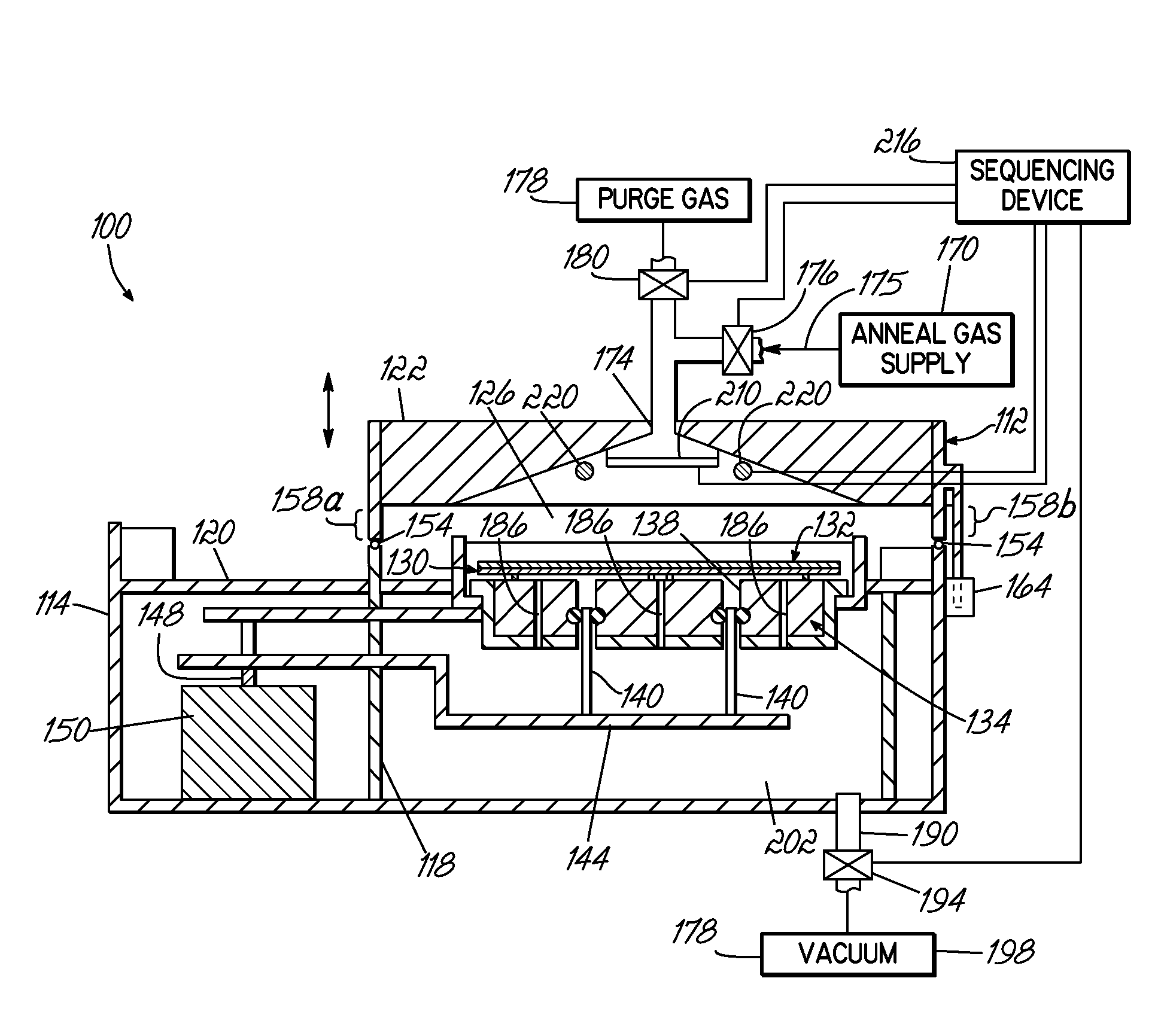
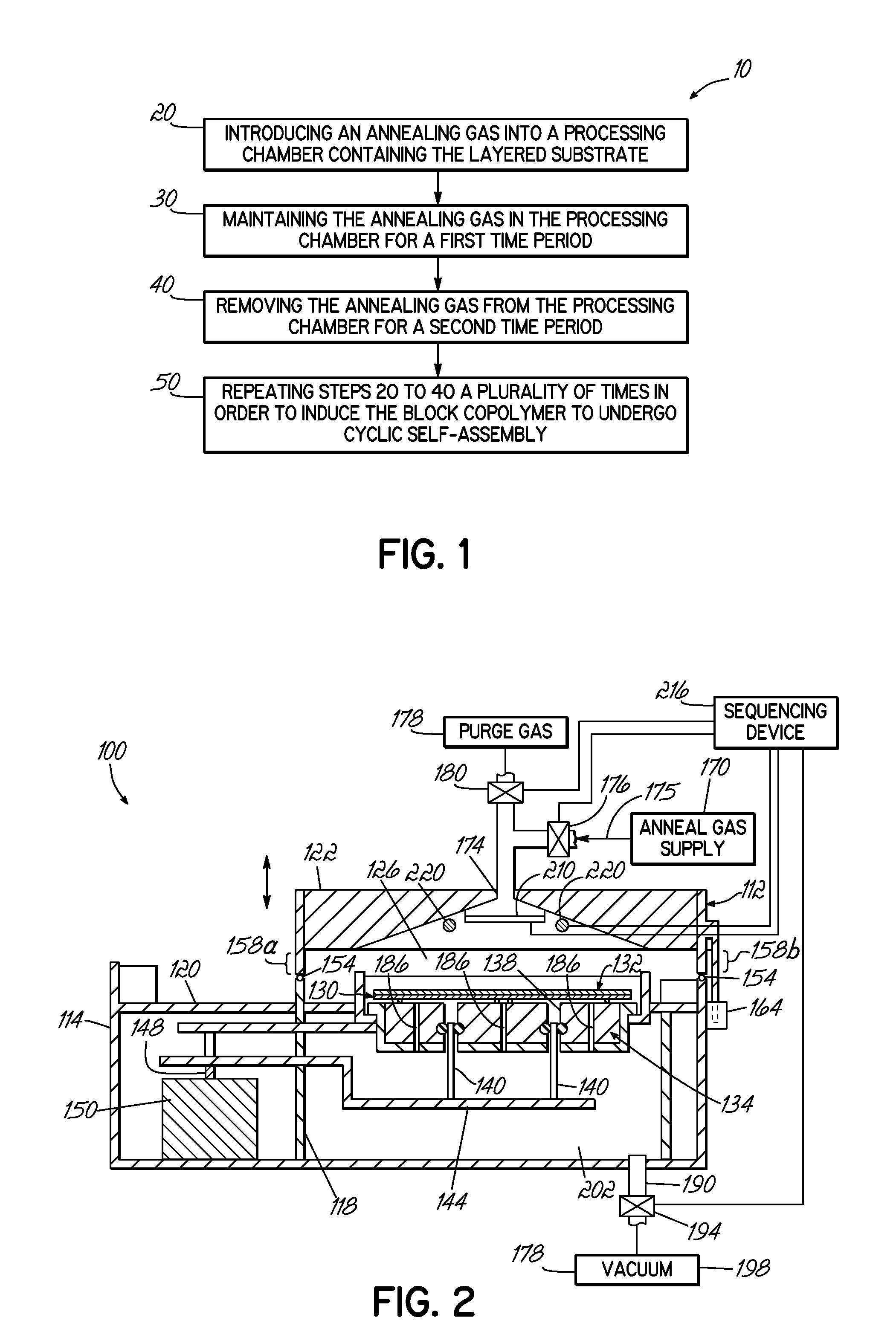
The present invention provides a method and apparatus for annealing a layer of a block copolymer for the purpose of directed self-assembly applications. The method involves introducing an annealing gas into a processing chamber containing the layer of block copolymer, maintaining the gas for a period of time to allow it to absorb into the layer, and then removing the gas to create an evaporation environment. This process helps to induce the block copolymer to undergo cyclic self-assembly. The apparatus includes a processor, a substrate support, an annealing gas supply, a heating element, an exhaust port, a purge gas supply, and a sequencing device that controls the settings of the gas supply, heating element, exhaust port, and purge gas supply. The technical effects of this invention are that it provides a more efficient and effective method for annealing block copolymers for directed self-assembly applications, leading to higher quality and more reliable results.

Problems solved by technology

Conventional thermal annealing of most block copolymers (e.g., PS-b-PVP, etc.) in air or vacuum will typically result in one block preferentially wetting the air vapor interface, which makes it more difficult to form the perpendicular oriented microdomains desirable for nanolithography.
Moreover, many high χ block copolymers possess order-disorder temperatures well above the block copolymers thermal degradation temperature making thermal annealing less practical.
However, traditional solvent vapor-assisted annealing is generally a very slow process, typically on the order of days, and can require large volumes of the solvent.

Method used


Image

  • Solvent anneal processing for directed-self assembly applications
  • Solvent anneal processing for directed-self assembly applications
  • Solvent anneal processing for directed-self assembly applications

Examples


Embodiment Construction

[0013]Apparatus and methods for solvent-assisted annealing of a substrate with direct self-assembly (“DSA”) integration are disclosed in various embodiments. However, one skilled in the relevant art will recognize that the various embodiments may be practiced without one or more of the specific details or with other replacement and / or additional methods, materials, or components. In other instances, well-known structures, materials, or operations are not shown or described in detail to avoid obscuring aspects of various embodiments of the present invention.

[0014]Similarly, for purposes of explanation, specific numbers, materials, and configurations are set forth in order to provide a thorough understanding. Nevertheless, the embodiments of the present invention may be practiced without specific details. Furthermore, it is understood that the illustrative representations are not necessarily drawn to scale.

[0015]Reference throughout this specification to “one embodiment” or “an embodi...


PUM


Abstract

A method and apparatus for solvent annealing a layered substrate including a layer of a block copolymer are provided. The method includes (a) introducing an annealing gas into a processing chamber; (b) maintaining the annealing gas in the processing chamber for a first time period; (c) removing the annealing gas from the processing chamber; and (d) repeating steps (a)-(c) a plurality of times in order induce the block copolymer to undergo cyclic self-assembly. The apparatus includes a processing chamber comprising a process space; a substrate support in the process space; an annealing gas supply and a purge gas supply, both in fluid communication with the process space; a heating element positioned within the processing chamber; an exhaust port in the processing chamber; and a sequencing device programmed to control the annealing gas supply, the heating element, the isolation valve of the exhaust port, and the purge gas supply.

Description

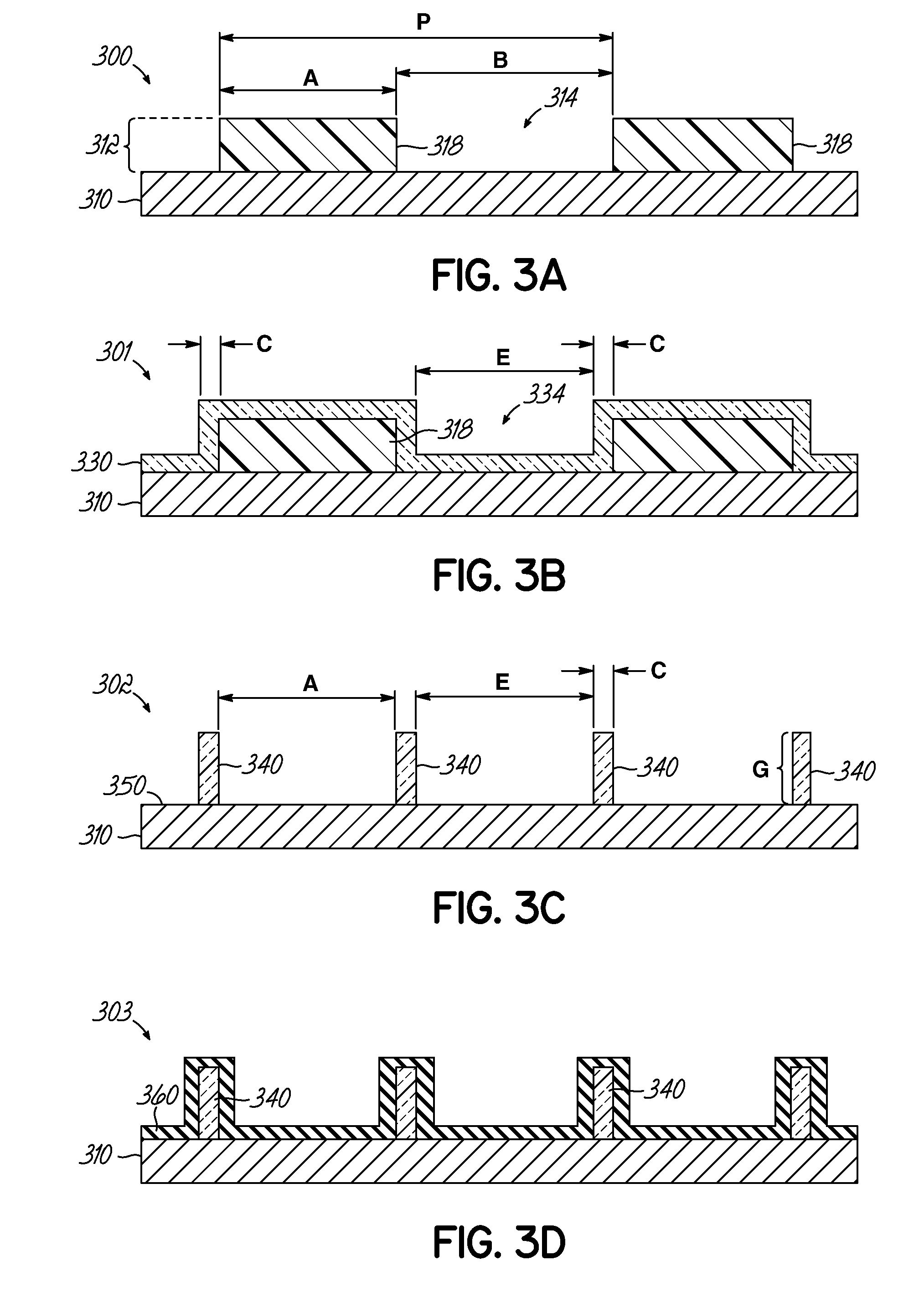
FIELD OF THE INVENTION[0001]The present invention relates generally to methods of fabricating semiconductor devices and, more specifically, to apparatus and methods of fabricating semiconductor devices using directed self-assembly processes.BACKGROUND OF THE INVENTION[0002]Directed self-assembly (“DSA”) processes use block copolymers to form lithographic structures. There are a host of different integrations for DSA (e.g., chemi-epitaxy, grapho-epitaxy, hole shrink, etc.), but in all cases the technique depends on the rearrangement of the block copolymer from a random, unordered state to a structured, ordered state that is useful for subsequent lithography. The morphology of the ordered state is variable and depends on a number of factors, including the relative molecular weight ratios of the block polymers. Common morphologies include line-space and cylindrical, although other structures may also be used. For example, other ordered morphologies include spherical, lamellar, bicontin...

Claims


Application Information

Patent Timeline
IPC IPC(8): H01L21/66H01L21/324
CPCH01L21/324H01L22/12G03F7/0002G03F7/168B82Y10/00B82Y40/00
Inventor SOMERVELL, MARK H.
Owner TOKYO ELECTRON LTD
Features
  • Generate Ideas
  • Intellectual Property
  • Life Sciences
  • Materials
  • Tech Scout
  • Unparalleled Data Quality
  • Higher Quality Content
  • 60% Fewer Hallucinations
Learn More