Differential electrical connector with improved skew control

a technology of electrical connectors and differential skews, applied in the direction of coupling device connections, electrical apparatus, coupling protective earth/shielding arrangements, etc., can solve the problems of electrical interference between adjacent signal conductors, electrical systems that are generally smaller, faster and functionally more complex, etc., and achieve the effect of improving skew control

Active Publication Date: 2014-09-18
AMPHENOL CORP
View PDF7 Cites 84 Cited by
  • Summary
  • Abstract
  • Description
  • Claims
  • Application Information

AI Technical Summary

Benefits of technology

[0008]An improved differential electrical connector is provided through improved skew control. The inventors have recognized and appreciated techniques for improving high frequency, differential connectors.

Problems solved by technology

Electronic systems have generally become smaller, faster and functionally more complex.
One of the difficulties in making a high density, high speed connector is that electrical conductors in the connector can be so close that there can be electrical interference between adjacent signal conductors.

Method used


Image

  • Differential electrical connector with improved skew control
  • Differential electrical connector with improved skew control
  • Differential electrical connector with improved skew control

Examples


Embodiment Construction

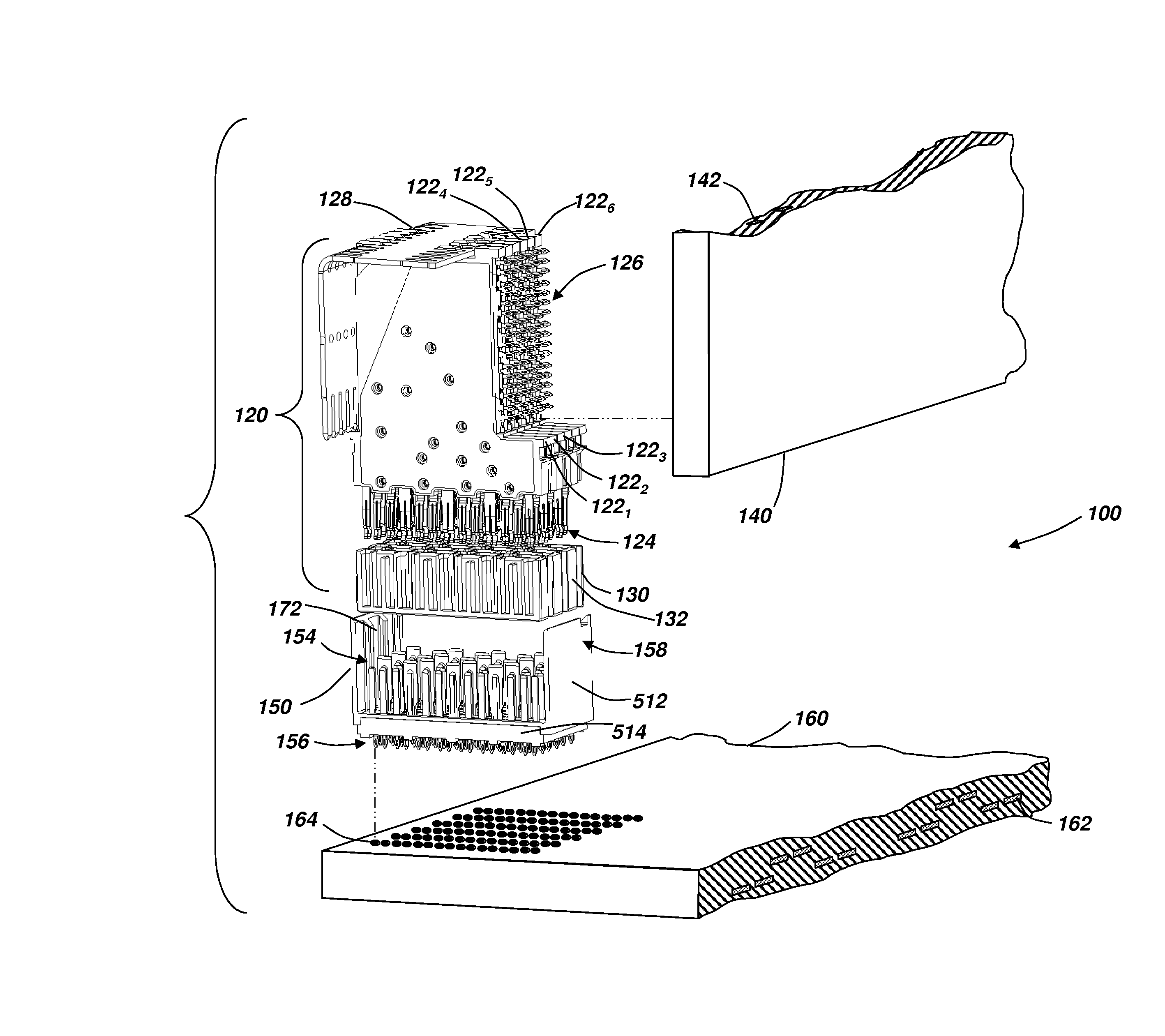
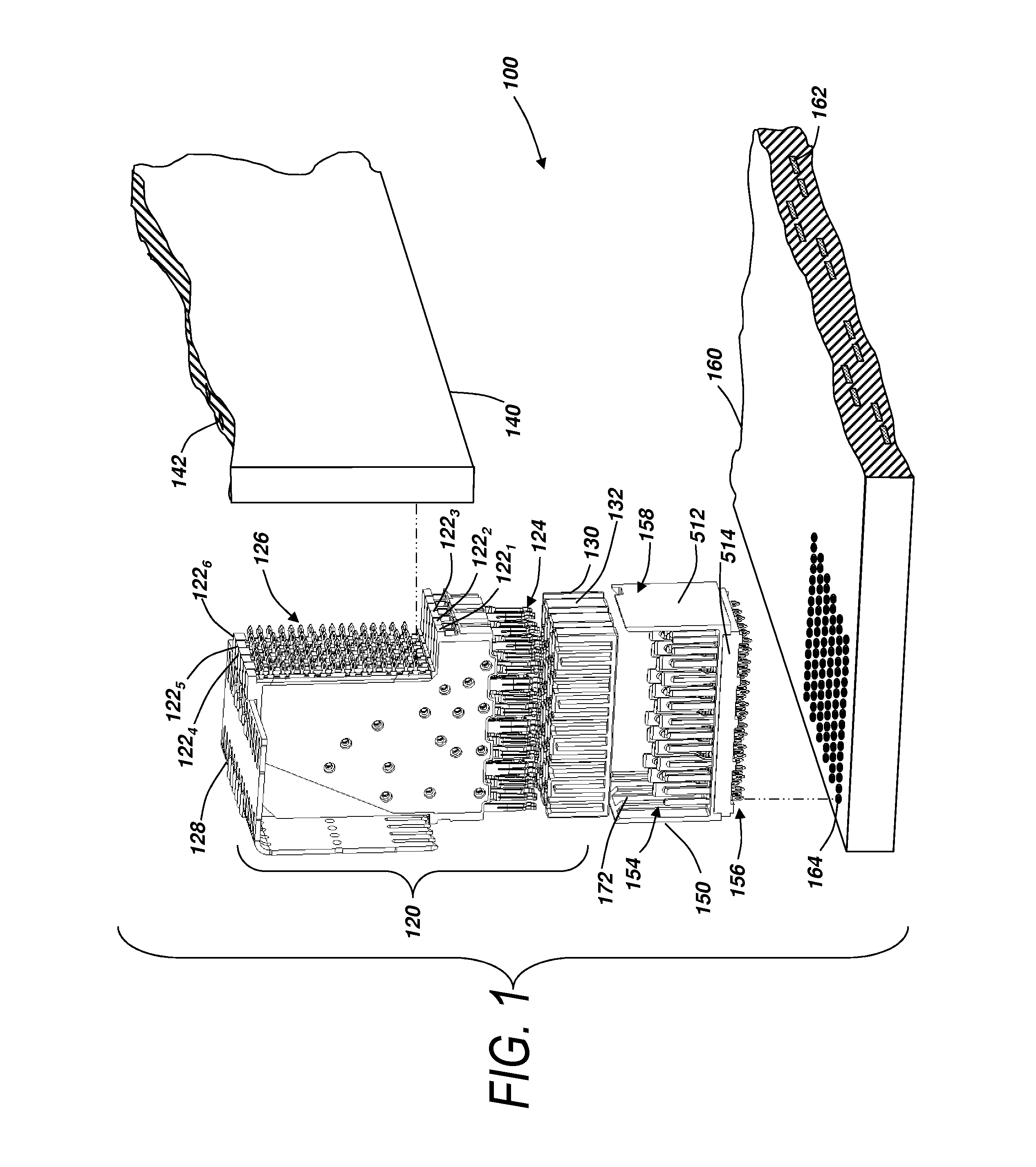
[0029]The inventors have recognized and appreciated that improved performance may be achieved in a differential electrical connector by incorporating skew compensation and compensation for impedance changes associated with skew compensation features into some or all of the differential pairs of a connector. The inventors have recognized and appreciated an approach to simply incorporate the features that provide skew compensation and impedance control into a high speed, high density electrical connector.

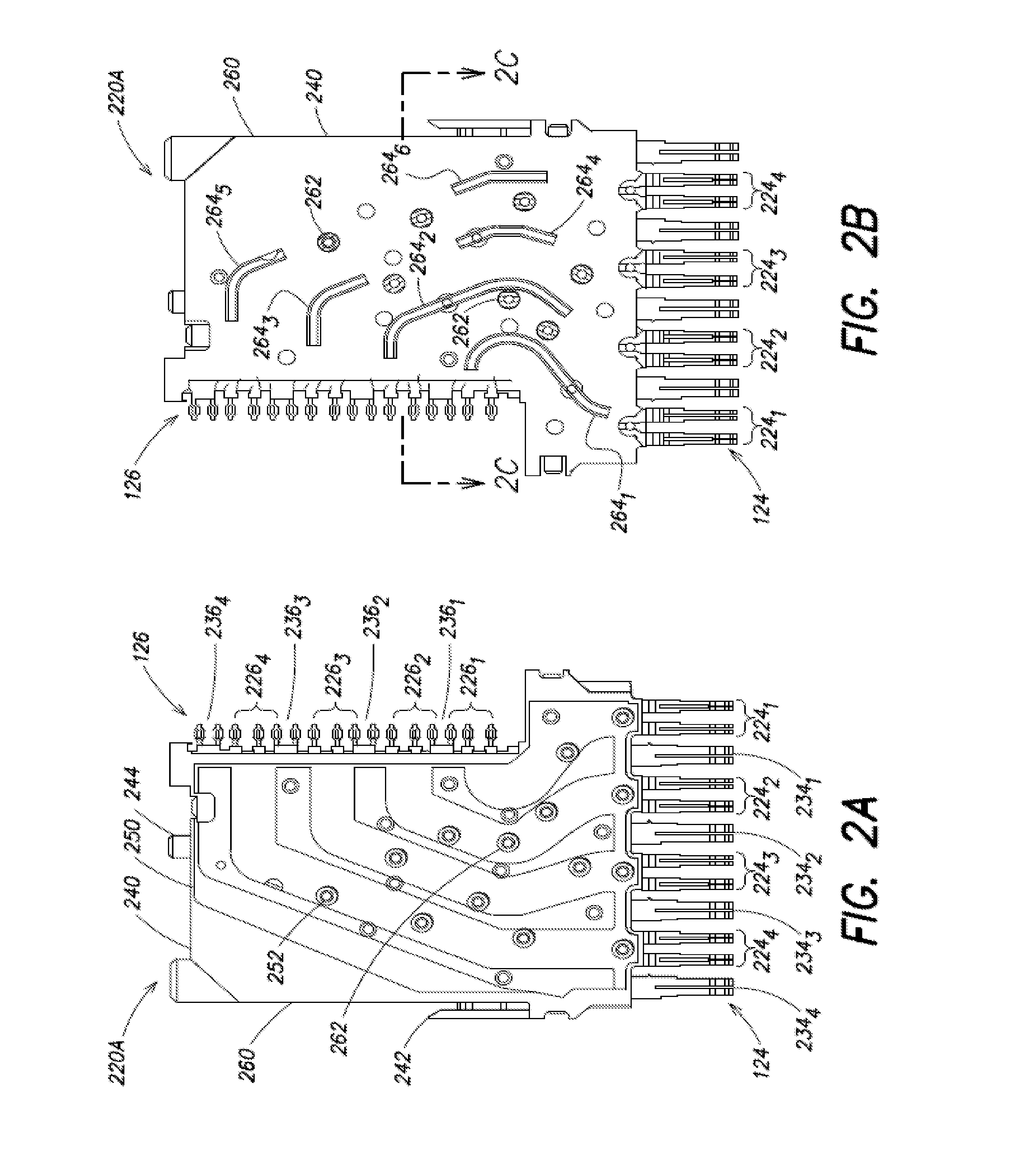
[0030]The skew compensation may be applied by creating a section of higher signal propagation speed along the longer conductive element of one or more of the differential pairs of the connector. Such skew compensation may be in the form of a region of lower dielectric constant material, such as a window, in an insulative housing above an intermediate portion of the conductive elements. The region may be selectively positioned over the longer conductive element of one or more of the di...


PUM


Abstract

An improved electrical connector is provided by compensating for skew in signal conductors of a differential pair while ensuring a uniform impedance along the differential pair. Skew is equalized by regions of lower dielectric constant preferentially positioned adjacent the longer conductor of each pair. Impedance along the length of the signal conductor is equalized by a compensation portion in the first conductor that offsets for a change in impedance associated with the change in dielectric constant adjacent the longer conductor. The compensation portion may be a widening in the first conductive element relative to a nominal width of the conductive element. The skew compensation portion may be along a longer edge of the longer conductor and the impedance compensation portion may be along the shorter edge of the longer conductor.

Description

RELATED APPLICATION[0001]The present application claims the benefit of U.S. Provisional Application Ser. No. 61 / 784,452, filed Mar. 14, 2013, which is hereby incorporated by reference herein in its entirety.BACKGROUND OF INVENTION[0002]This invention relates generally to electrical interconnection systems and more specifically to improved signal integrity in interconnection systems, particularly in high speed electrical connectors.[0003]Electrical connectors are used in many electronic systems. It is generally easier and more cost effective to manufacture a system on several printed circuit boards (“PCBs”) that are connected to one another by electrical connectors than to manufacture a system as a single assembly. A traditional arrangement for interconnecting several PCBs is to have one PCB serve as a backplane. Other PCBs, which are called daughter boards or daughter cards, are then connected through the backplane by electrical connectors.[0004]Electronic systems have generally bec...

Claims


Application Information

Patent Timeline
Patent Type & Authority Applications(United States)
IPC IPC(8): H01R13/502H01R13/658
CPCH01R13/658H01R13/502H01R12/724H01R13/514H01R13/6476H01R43/16H01R43/24
Inventor CARTIER, JR., MARC B.GAILUS, MARK W.SIVARAJAN, VYSAKH
Owner AMPHENOL CORP
Why Eureka
Try Eureka