Fault Tolerant Control System

a control system and fault-tolerant technology, applied in the direction of program control, instruments, safety arrangements, etc., to achieve the effect of reducing the risk of system failure and reducing the risk associated

Active Publication Date: 2014-09-18
GM GLOBAL TECH OPERATIONS LLC
View PDF59 Cites 32 Cited by
  • Summary
  • Abstract
  • Description
  • Claims
  • Application Information

AI Technical Summary

Benefits of technology

[0003]An advantage of an embodiment is continued functionality of a system that utilizes duplex controllers, where functionality of system is maintained despite a failure in the system, such as a software design defect, which would otherwise affect both controllers thereby having no behavior responses from either controller. More so, the feasibility of starting either controller within microseconds provides a simple safe operating mode of operation which allows a control device operation to run as a separate application on bare hardware with minimal operating system support. The invention described herein combines the advantages of physical redundancy with an incremental fallback strategy with the overall goal of avoiding a condition in which the automation is unable to maintain a state of operation before the driver can be reasonably expected to take back control of the vehicle. The physical redundancy of this design primarily mitigates the risk of system failure due to random hardware faults. In addition, the incremental fallback from normal mode operation to safe mode operation primarily mitigates risk associated with systematic failures, e.g., software defect.

Problems solved by technology

The physical redundancy of this design primarily mitigates the risk of system failure due to random hardware faults.
In addition, the incremental fallback from normal mode operation to safe mode operation primarily mitigates risk associated with systematic failures, e.g., software defect.

Method used


Image

  • Fault Tolerant Control System
  • Fault Tolerant Control System
  • Fault Tolerant Control System

Examples


Embodiment Construction

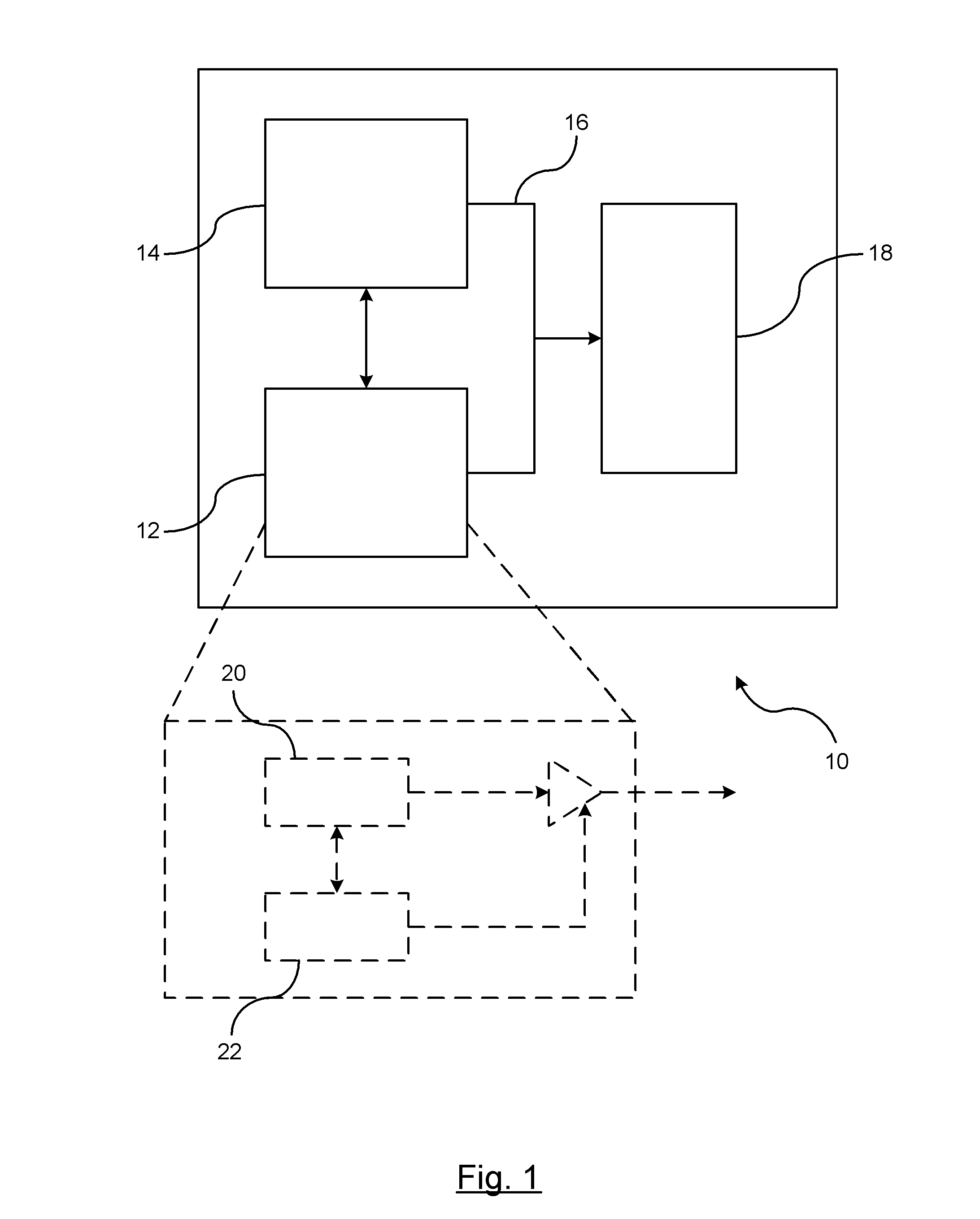
[0009]There is shown in FIG. 1 an architectural block diagram of a duplex controller for a vehicle fail-operational system. Typically, vehicle systems utilize two controllers if the controlled system is one that utilizes autonomous controls or a safety-critical system, and therefore, requires fault-tolerant countermeasures if an error occurs within the system. The term autonomous controls or autonomous operation as used herein may refer to fully autonomous operations, semi-autonomous operations, or limited autonomous operations. Examples of such systems include, but are not limited to, autonomous driving systems such as adaptive cruise control systems and automated parking systems. In FIG. 1, a vehicle 10 is shown to include a first controller 12 and a second controller 14, a communication bus 16, and a vehicle device 18 (e.g., actuation device) for actuating a vehicle operation for preferably performing an automated operation that is controlled by the first controller 12 and the se...


PUM


Abstract

A fault tolerant controller system includes a first controller and a second controller. One of the first and second controllers designated as a primary controller for generating control signals intended to control actuation devices on a vehicle under non-fault operating conditions, and the other of the first and second controllers designated as a secondary controller generating control signals intended to control actuation devices on the vehicle. The actuation devices are responsive only to the designated primary controller. An error is detected in the primary controller and a message is transmitted from the faulty controller to the non-faulty controller identifying the error. The non-faulty controller is subsequently designated as the primary controller. The control signals including an identifier that identifies the non-faulty controller as the designated primary controller. In response to detecting the error, the faulty controller is reset to operate in a safe operating mode as the secondary controller.

Description

BACKGROUND OF INVENTION[0001]An embodiment relates generally to fault control in fail-operational vehicle systems.[0002]Systems which provide safety functions typically utilize redundant controllers to ensure that safe operation can be continued for a duration of time to allow the system to transition to a mode of operation that does not depend on the current state of the failed operational system. Such systems typically utilize dual duplex controllers. If a first controller fails and falls silent, a second controller will be activated and all actuators will switch over to rely on requests from the second controller. The system will function properly if the defect was something that was hardware in nature (e.g., wiring issue, pin connect issue), such that the second controller does not have the same defect. However, if the defect is due to a defect that is common to both controllers, such as a software defect, then this software defect causes a runtime error that both controllers ar...

Claims


Application Information

Patent Timeline
Patent Type & Authority Applications(United States)
IPC IPC(8): G05B9/02
CPCG05B9/02B60W50/023G05B9/03G05B2219/24187G05B2219/24198G05B2219/24208
Inventor DEBOUK, RAMI I.BAKER, STEPHEN M.JOYCE, JEFFREY
Owner GM GLOBAL TECH OPERATIONS LLC
Why Eureka
Try Eureka