Controlling an HVAC system in association with a demand-response event

a technology of hvac system and demand response, applied in the direction of instruments, heating types, static/dynamic balance measurement, etc., can solve the problems of increasing demand, increasing electricity demand, and often prohibitive costs of doing so, and achieve the effect of minimizing a cost function

Active Publication Date: 2014-09-18
GOOGLE LLC
View PDF10 Cites 101 Cited by
  • Summary
  • Abstract
  • Description
  • Claims
  • Application Information

AI Technical Summary

Benefits of technology

[0010]Various methods for carrying out demand response (DR) events are disclosed. According to one embodiment, a method for carrying out a DR event via an intelligent, network-connected thermostat associated with a structure, includes a variety of operations. Such operations include identifying a DR event that defines a DR event period, and determining an optimized control trajectory of a heating, ventilation, and air conditioning (HVAC) system to be in effect during the DR event period that minimizes a cost function. The cost function may be a combination of a variety of factors, such as a first factor representative of a total energy consumption during the DR event period, a second factor representative of a metric of occupant discomfort, and a third factor representative of deviations of a rate of energy consumption over the DR event period. The operations may further include controlling the HVAC system in accordance with the determined optimized control trajectory.

Problems solved by technology

Utility companies face ongoing challenges with consistently satisfying the demand for electricity.
However, consumers' demand for electricity is often quite the opposite in that the aggregate electricity demand varies significantly over the course of the delay.
For example, during the summertime, demand generally tends to increase as the outside temperature increases to levels considered uncomfortable as consumers increase their usage of high consumption appliances such as air conditioning systems.
However, the costs of doing so are often prohibitive and building such plants is often inefficient as the added capacity is used for only short durations throughout the year.
They may buy additional capacity from other utility company's or energy providers, but doing so is also costly as such company's may charge a premium and the energy transfer from those other companies is often less efficient.
Such control, of course, often creates an inconvenience to the consumers who sign up to participate in such a ‘demand response program’ as their cooling system may not cool their residence as expected.
Consumers may express some degree of animosity towards such a technique, however, as direct load control results in a lack of control by the consumer of their cooling system, and often results in inside temperatures that are found to be uncomfortable by the consumer.
Deficiencies in the communication link between the utility company and the switch can worsen the problem, with lost commands from the utility company to the switch to reconnect power to the cooling system resulting in the cooling system undesirably remaining in a disconnected state.
Such problems have resulted in some consumers attempting to obviate the control on their cooling system while still attaining the benefits of participating in the demand response program by bypassing the remotely controlled switch.
As a result, while such “cheaters” may acquire their desired individual cooling system control, the effectiveness of the overall demand response program can be undermined.
While providing the potential for increased comfort and acceptance over direct on / off cycling of the power to the cooling system by the utility, this technique can have disadvantages including lack of control by the consumer and the utility company's ability to set the setback value to any value the utility company deems suitable.
Moreover, the use of a single setback value for all consumers fails to recognize differences in perceptions in comfort, differences in thermal characteristics of residences, differences in cooling capacities of the cooling systems, and other differences among the base of participating customers.
By way of example, although the above described methods of direct load control, temperature setback control, and direct load control followed by temperature setback control will generally result in some amount of reduced energy use during the load shedding event across the base of participating customers, such “one-size-fits-all” approaches to the customer base can result in substantial missed opportunities for more effective load shifting and reduced customer inconvenience.

Method used


Image

  • Controlling an HVAC system in association with a demand-response event
  • Controlling an HVAC system in association with a demand-response event
  • Controlling an HVAC system in association with a demand-response event

Examples


Embodiment Construction

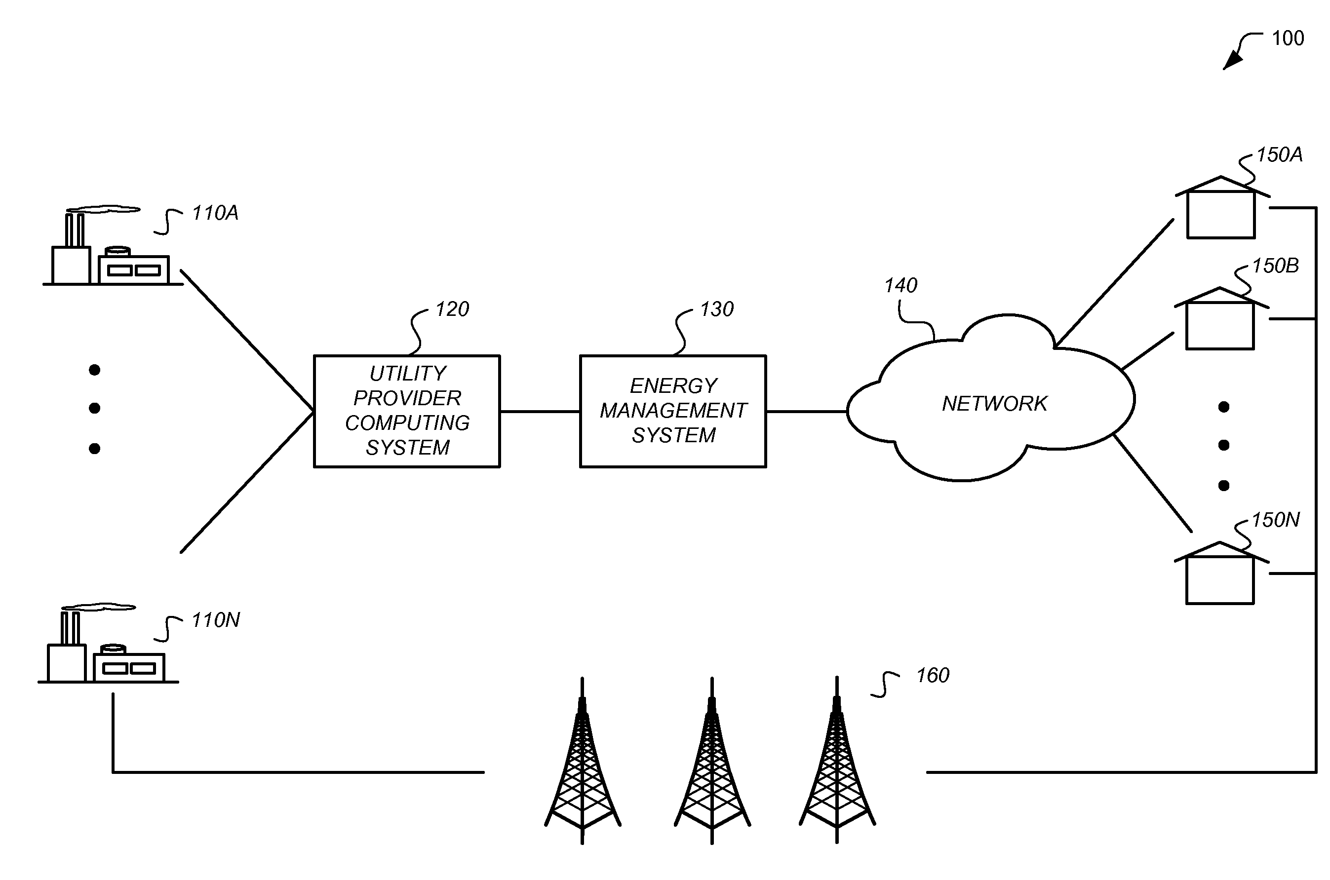
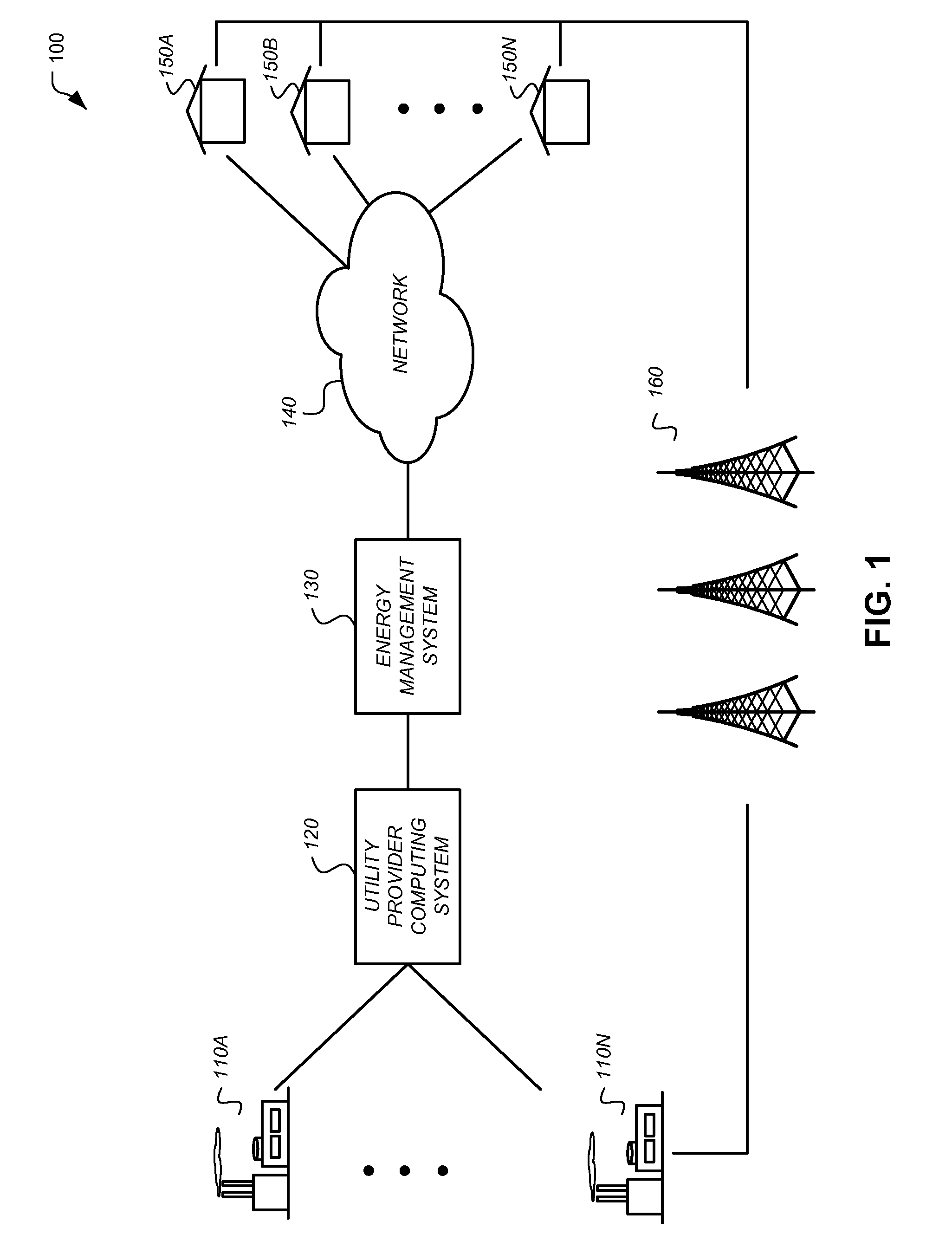
[0039]Embodiments of the present invention generally relate to techniques for controlling an HVAC system during a demand-response event. The entities in a system for controlling an HVAC system during a demand-response event typically include a utility provider that provides electrical or other forms of energy from a power source (e.g., an electrical generator) to individuals' homes or businesses. The individuals typically pay for the amount of energy they consume on a periodic, e.g., monthly, basis. In many embodiments an energy management system is disposed between the utility provider and the individuals. The energy management system operates to intelligently and effectively shift energy consumption of the individuals from one particular time period to other time periods. Such energy shifting is usually performed so as to shift energy consumption from a high energy cost period to a low energy cost period. In the case of DR events, energy is shifted from the DR event period to time...


PUM


Abstract

Apparatus, systems, methods, and related computer program products for carrying out a demand response (DR) event via an intelligent, network-connected thermostat associated with a structure. The systems disclosed include an energy management system in operation with an intelligent, network-connected thermostat located at a structure. The thermostat is operable to control an HVAC system. Control during a DR event period may be performed based on an optimal control trajectory of the HVAC system, where the control trajectory is optimal in that it minimizes a cost function comprising a combination of a first factor representative of a total energy consumption during the DR event period, a second factor representative of a metric of occupant discomfort, and a third factor representative of deviations of a rate of energy consumption over the DR event period.

Description

RELATED APPLICATIONS[0001]This application claims the benefit of and is a continuation-in-part of U.S. Ser. No. 13 / 842,213, filed Mar. 15, 2013, the entire contents of which are incorporated by reference herein in their entirety for all purposes.FIELD[0002]This patent specification relates to systems, apparatus, methods, and related computer program products for controlling an HVAC system during a demand-response event. More particularly, this patent specification relates to techniques for intelligently selecting and / or optimizing a control trajectory of an HVAC system during a demand-response event.BACKGROUND[0003]Utility companies face ongoing challenges with consistently satisfying the demand for electricity. Facilities for generating electricity are typically well-suited for supplying constant amounts of electricity. However, consumers' demand for electricity is often quite the opposite in that the aggregate electricity demand varies significantly over the course of the delay. T...

Claims


Application Information

Patent Timeline
Patent Type & Authority Applications(United States)
IPC IPC(8): G05D23/19
CPCG05D23/19G05D23/1904G05D23/1905F24F2140/60F24F2120/20F24F11/62F24F11/30F24F11/64
Inventor MATSUOKA, YOKYMALHOTRA, MARKMINICH, ALLEN J.STEFANSKI, MARK D.
Owner GOOGLE LLC
Why Eureka
Try Eureka