Fuel consumption compensation for evaporative emissions system leak detection methods

a technology of evaporative emissions and leak detection, which is applied in the direction of instruments, machines/engines, mechanical equipment, etc., can solve problems such as influencing the pressure of the evap system

Inactive Publication Date: 2014-09-18
DELPHI TECH INC
View PDF4 Cites 23 Cited by
  • Summary
  • Abstract
  • Description
  • Claims
  • Application Information

AI Technical Summary

Benefits of technology

[0003]In accordance with one embodiment, a method for monitoring an evaporative emissions control (EVAP) system is provided. The method includes compensating a diagnostic test of the EVAP system based on a fuel consumption amount during a test interval.
[0004]In accordance with one embodiment, a method for monitoring an EVAP system in a vehicle is provided. The system includes a fuel tank. The system also includes a vent valve operable to an open state that allows fluidic communication through the vent valve between the EVAP system and atmosphere, and a closed state that blocks fluidic communication through the vent valve. The system also includes a purge valve operable to an open state that allows fluidic communication through the purge valve between the EVAP system and the intake manifold of the engine, and a closed state that blocks fluidic communication through the purge valve. The method includes the step of establishing a leak test pressure in the EVAP system. The method also includes the step of operating the vent valve and the purge valve to the closed state. The method also includes the step of determining an actual pressure change of the EVAP system. The method also includes the step of determining an expected pressure change in the EVAP system based on vehicle operating conditions that include the fuel consumption amount. The method also includes the step of indicating that a leak is detected if the actual pressure change differs from the expected pressure change by more than a difference threshold.
[0005]In accordance with one embodiment, a method of detecting a leak of an EVAP system in a vehicle is provided. The EVAP system includes a fuel tank. The EVAP system also includes a vent valve operable to an open state that allows fluidic communication through the vent valve between the EVAP system and atmosphere, and a closed state that blocks fluidic communication through the vent valve. The system also includes a purge valve operable to an open state that allows fluidic communication through the purge valve between the EVAP system and the intake manifold of the engine, and a closed state that blocks fluidic communication through the purge valve. The method includes the step of reducing EVAP system pressure to a leak test pressure less than atmospheric pressure. The method also includes the step of operating the vent valve and the purge valve to the closed state. The method also includes the step of determining an actual pressure increase of the EVAP system. The method also includes the step of determining an expected pressure change based on vehicle operating conditions that include a fuel consumption amount. The method also includes the step...

Problems solved by technology

The engine's consumption of fuel from the fuel...

Method used


Image

  • Fuel consumption compensation for evaporative emissions system leak detection methods
  • Fuel consumption compensation for evaporative emissions system leak detection methods
  • Fuel consumption compensation for evaporative emissions system leak detection methods

Examples


Embodiment Construction

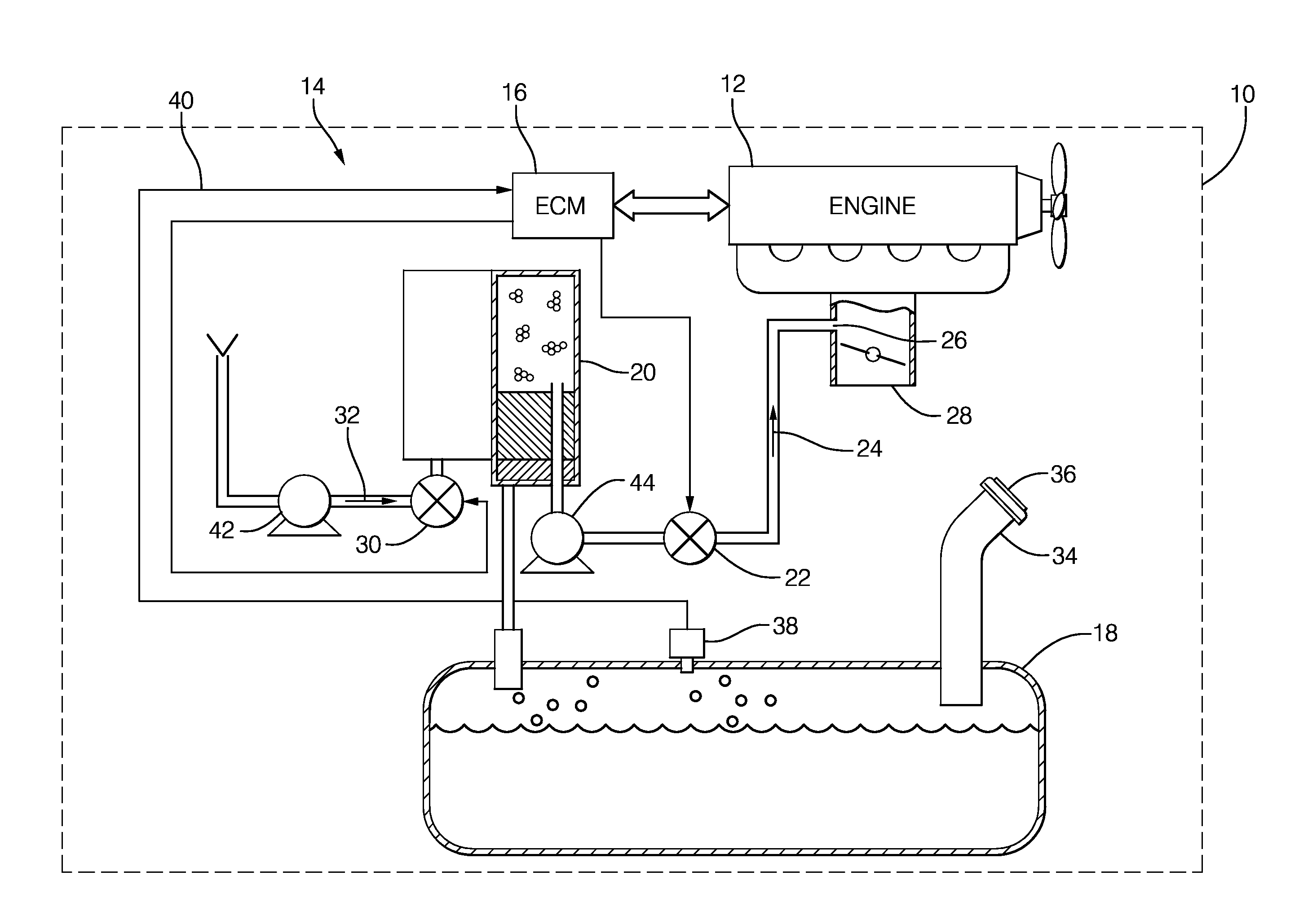
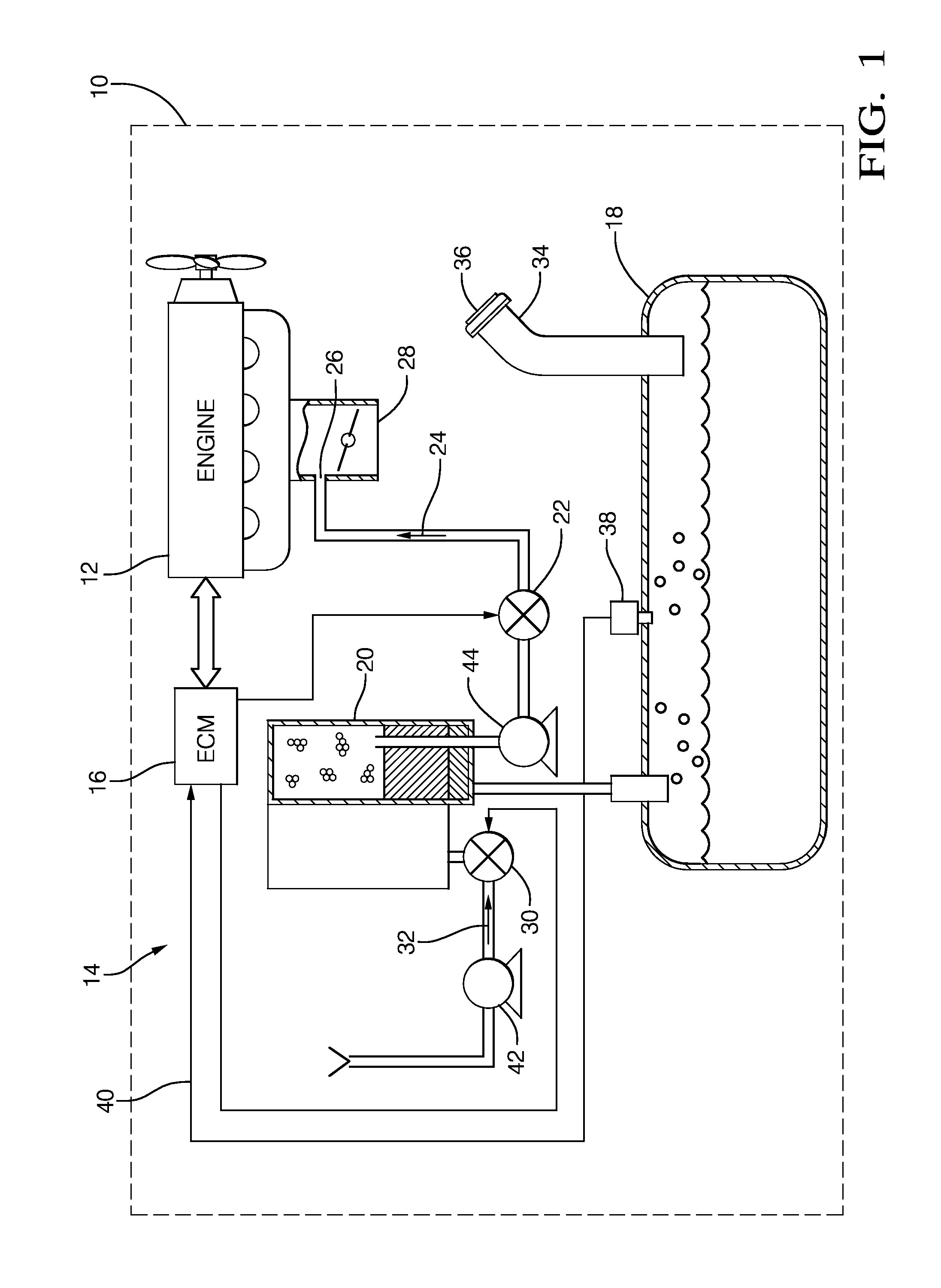
[0015]While investigating ways to improve the prediction of the change of EVAP system pressure during a leak test, it was discovered that fuel consumption may be a dominate cause of change in the EVAP system pressure. The terms ‘EVAP system pressure’, ‘(fuel) tank pressure’, ‘EVAP system vacuum’, and ‘(fuel) tank vacuum’ may be used interchangeable throughout the following description. The terms ‘EVAP system pressure’, ‘tank pressure’, ‘fuel tank vacuum’, and ‘tank vacuum’ may be used interchangeable throughout the following description. In some instances ‘pressure’ is use to indicate an absolute pressure or gauge pressure, while ‘vacuum’ is generally used to indicate a pressure difference between atmospheric pressure outside the EVAP system and a reduced pressure relative to the atmospheric pressure present within the EVAP system.

[0016]Known EVAP systems often wait for engine idle / vehicle not moving conditions to perform tests of the EVAP system. However, because some vehicle are c...


PUM


Abstract

A method for monitoring an evaporative emissions control (EVAP) system that includes compensating a diagnostic leakage test based on a fuel consumption amount during a test interval is disclosed. The method includes establishing a leak test pressure in the EVAP system, operating the operating the associated valves and pumps such that the EVAP system is expected to be isolated, determining an actual pressure change of the EVAP system, determining an expected pressure change of the EVAP system based on vehicle operating conditions that include the fuel consumption amount, and indicating that a leak is detected if the actual pressure change differs from the expected pressure change by more than a difference threshold.

Description

TECHNICAL FIELD OF INVENTION[0001]This disclosure generally relates to detecting leaks in a vehicle evaporative emissions control (EVAP) system, and more particularly relates to compensating the threshold used to detect a leak for the effects of fuel consumption during an EVAP system diagnostic test.BACKGROUND OF INVENTION[0002]Government regulations require that vehicles be configured to perform self-diagnostic testing of the evaporative emissions control (EVAP) system on the vehicle. Typically, the pressure inside the EVAP system, which is indicated by a pressure sensor that is typically mounted inside the fuel tank (i.e., EVAP system pressure), is changed to a predetermined leak test pressure that is less than or greater than atmospheric pressure by either vacuum from a running engine, a pressure pump, or a vacuum pump to create certain conditions in the EVAP system so diagnostic testing can be performed. One regulation requires that a leak equivalent to a 0.5 millimeter (mm) hol...

Claims


Application Information

Patent Timeline
IPC IPC(8): F02M25/08
CPCF02M25/0818
Inventor GUO, YICHAOSIMPSON, KENNETH M.JEFFERS, JAMES W.
Owner DELPHI TECH INC
Why Eureka
Try Eureka