Aircraft taxiing system

a taxiing system and aircraft technology, applied in the field of aircraft taxiing, can solve the problems of pilot distraction, large number of airport accidents, and increased fuel burn, and achieve the effects of safe taxiing, avoiding collisions and incursions, and safe taxiing

Inactive Publication Date: 2014-09-18
HONEYWELL INT INC
View PDF11 Cites 35 Cited by
  • Summary
  • Abstract
  • Description
  • Claims
  • Application Information

AI Technical Summary

Benefits of technology

[0007]In a third aspect of the present invention, a method of taxiing an aircraft at an airport is provided, comprising: receiving runway advisories from a Runway Awareness and Advisory System (RASS); receiving GPS / Inertial / Radio Navigation and air traffic control (ATC) cleared taxi route from at least one data input source; receiving traffic collision alerts from a traffic collision avoidance system (TCAS); calculating steering commands in response to the taxi route data, the runway advisories, and the collision avoidance alerts; if the aircraft is equipped with an electric taxi system: activating the electric taxi system; and transmitting the steering commands to the electric taxi system to safely taxi the aircraft along the taxi route avoiding collisions and incursions; and if the aircraft is not equipped with an electric taxi system: transmitting the steering commands to one or more of an auto-throttle subsystem, a nose wheel steering sub system, and a brake control subsystem to safely taxi the aircraft along the taxi route avoiding collisions and incursions.

Problems solved by technology

In addition, the more turns or stops an aircraft makes during taxiing, the more fuel is burned.
Runway incursions account for a large number of airport accidents.
During taxi-out, the pilot may be distracted by pre-takeoff activities and may not be fully focused on guiding the aircraft to the runway.
Weather-related issues, such as excessive speed on snow or ice or in poor visibility, may be a factor in accidents, as well.
Other accidents may be the result of collisions with other taxiing aircraft or ground vehicles.

Method used


Image

  • Aircraft taxiing system
  • Aircraft taxiing system
  • Aircraft taxiing system

Examples


Embodiment Construction

[0012]The following detailed description is of the best currently contemplated modes of carrying out exemplary embodiments of the invention. The description is not to be taken in a limiting sense, but is made merely for the purpose of illustrating the general principles of the invention, since the scope of the invention is best defined by the appended claims.

[0013]Various inventive features are described below that can each be used independently of one another or in combination with other features.

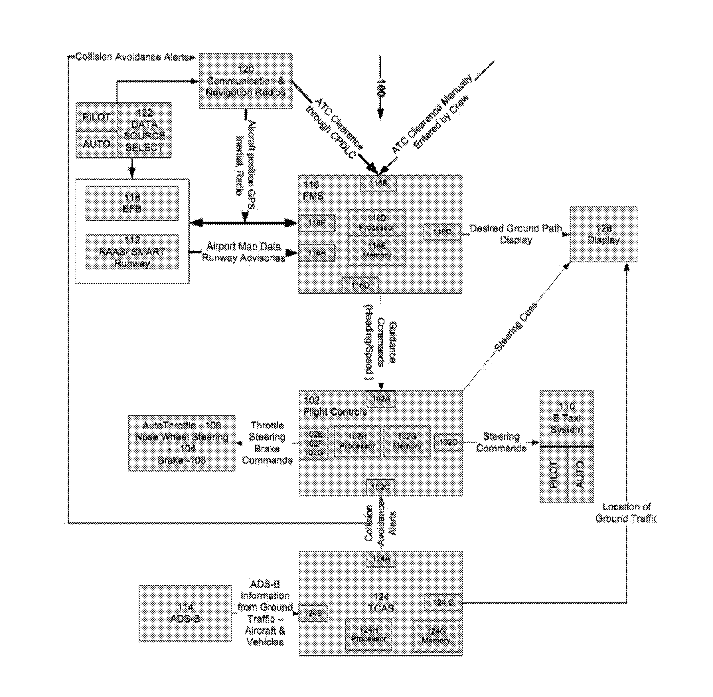
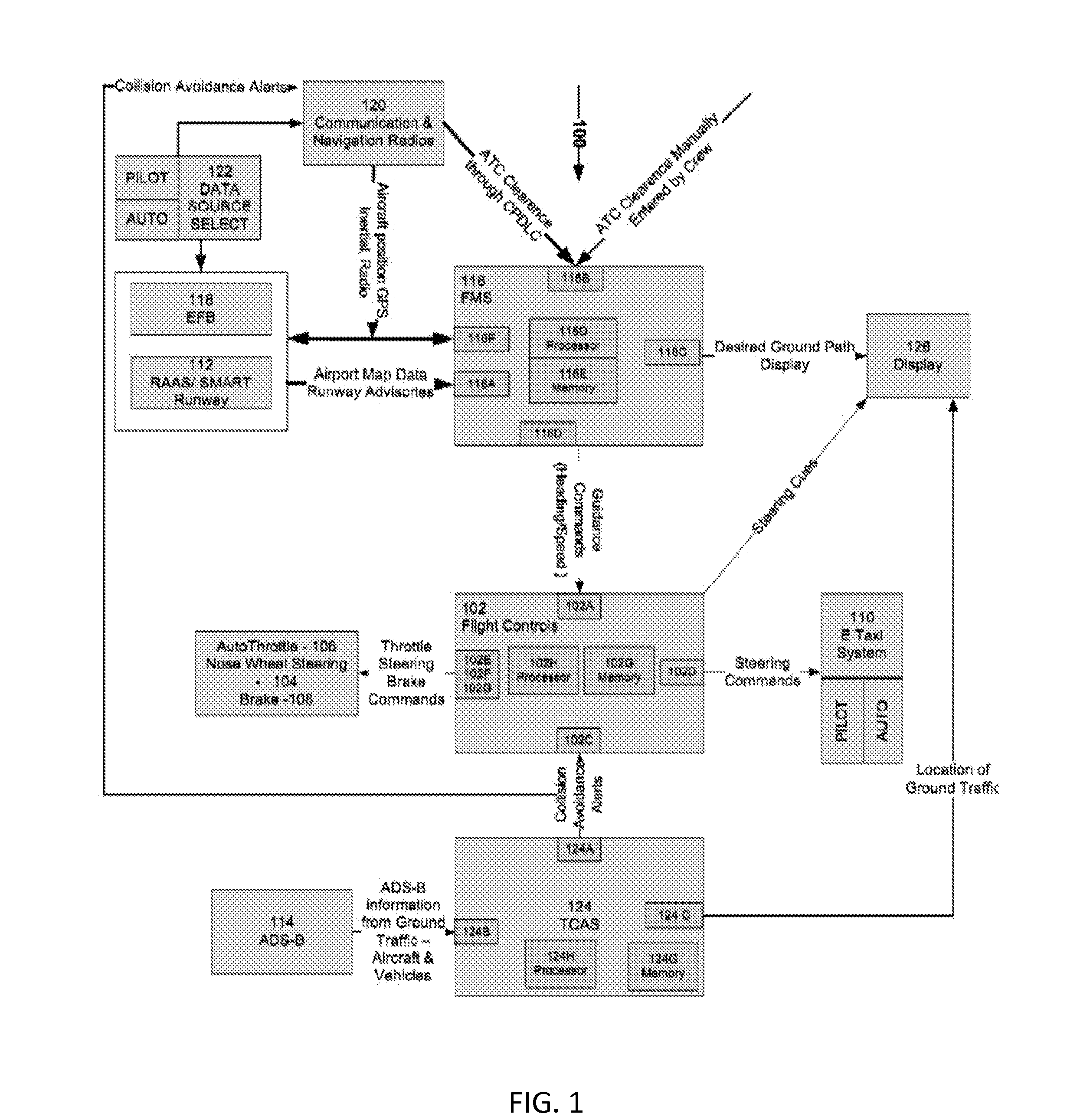
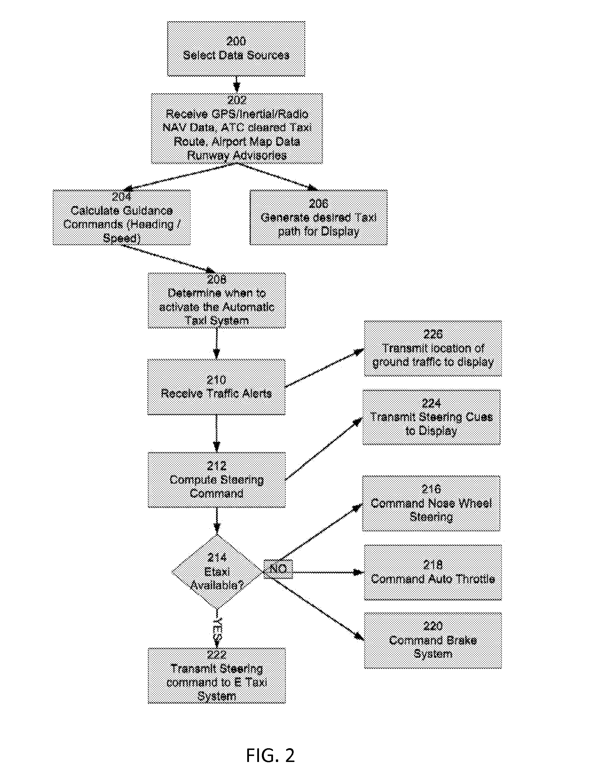
[0014]Broadly, embodiments of the present invention generally provide an aircraft taxiing system that may improve both ground safety and fuel efficiency. An aircraft's flight control system may be coupled to an electric taxi system or a combination of the auto throttle, nose wheel steering and braking systems and information received from air traffic control and other sources may allow the aircraft to automatically taxi from gate to runway and from runway to gate in a manner that reduces s...


PUM


Abstract

An aircraft taxiing system is provided, comprising a flight control system, an electric taxi system having controls, a flight management system (FMS), at least one data input source coupled to the FMS, and a traffic collision avoidance system (TCAS). The FMS is programmed with instructions to calculate guidance speed and heading commands, augment the guidance commands to avoid runway incursions, and transmit the guidance commands to the flight control system. The TCAS is programmed with instructions to receive Automatic Dependent Surveillance-Broadcast (ADS-B) data from ground traffic, generate collision avoidance alerts; and transmit the collision avoidance alerts to the flight control system. The flight control system is programmed with instructions to receive guidance commands from the FMS, receive the traffic collision avoidance alerts from the TCAS, and compute the steering commands, and transmit the commands to the electric taxi system to taxi the aircraft along a calculated taxi route.

Description

BACKGROUND OF THE INVENTION[0001]The present invention generally relates to aircraft taxiing and, in particular, to a taxiing system to facilitate the safe and efficient movement of aircraft on the ground.[0002]Taxiing is the movement of an aircraft on the ground from the gate to the runway prior to takeoff and from the runway to the gate after landing. The taxi-out phase of an aircraft accounts for a significant percentage of the total fuel burned from the origination gate to the destination gate. In addition, the more turns or stops an aircraft makes during taxiing, the more fuel is burned.[0003]Runway incursions account for a large number of airport accidents. During taxi-out, the pilot may be distracted by pre-takeoff activities and may not be fully focused on guiding the aircraft to the runway. Weather-related issues, such as excessive speed on snow or ice or in poor visibility, may be a factor in accidents, as well. Other accidents may be the result of collisions with other ta...

Claims


Application Information

Patent Timeline
Patent Type & Authority Applications(United States)
IPC IPC(8): G08G5/06
CPCG08G5/065G08G5/0021
Inventor CHOKSI, HARDIKSAINUDEEN, RAFEEKSHAM, NAGARAJ
Owner HONEYWELL INT INC
Why Eureka
Try Eureka