Method and system for controlling and eliminating pests

a technology for pests and pests, applied in the field of pest control, can solve the problems of pest infestation, weighing loss, loss, etc., and achieve the effect of reliable estimation and waste of human resources

Inactive Publication Date: 2014-09-25
ATTAX DEDETIZACAO DESRATIZACAO S C LTDA ME
View PDF0 Cites 24 Cited by
  • Summary
  • Abstract
  • Description
  • Claims
  • Application Information

AI Technical Summary

Benefits of technology

[0008]Many traps for flying insects are based in a cone-shaped element such as shown in FIGS. 3, 4 and 5. FIG. 3 is an exploded view of the trap disclosed in patent application BR8800309-4 Disposição Aplicada em Armadilha para Moscas e Insetos Dipteros em Geral (Arrangement Applied in Trap for Flies and Dipterous Insects in General). As shown in the drawings, the trap comprises a vessel generally shaped as a cylinder 9, over whose lower base rests a truncated cone 4 provided, in its upper base V, with openings that allow an insect to go through. The void between the inner wall of the cylinder and the outer wall of the truncated cone is shaped as a circular channel 15 filled in part with a liquid that attracts insects 14. As shown in FIG. 4, an insect M is attracted by the liquid's odor and enters the trap flying upward inside the truncated cone. After passing through the apertures in said upper base V the insect remains imprisoned in void 15 and eventually falls into the liquid 14 where it drowns. For use in closed spaces, the trap can be suspended by eyelet 7. FIG. 5 shows the arrangement used outdoors, such as in gardens for instance, comprising a supporting element 25 associated with a vertical rod 26 whose lower end is inserted into the ground.
[0009]To inspect the trap's conditions the insect retaining element, i.e. the sieve 3 is lifted by the tabs 10, in order to avoid loss of the attractant solution 14. A shortcoming of this trap is the fact that the period between inspections may be too short for trapping a substantial amount of insects. Moreover, the number of insects retained in the sieve has to be counted by the operator, a time-consuming activity whose accuracy depends on the operator's ability.
[0010]In brief, the state of the art traps have in common the drawback of not allowing a straightforward estimate of the extent of vermin infestation in the locality in which the traps are deployed, allowing only a rough approximation of the number of trapped pests based on the results of the operator's manual inspections. In point of fact, due to the fact that the existence of rodents or insects is only substantiated when the dead animals are removed during the regular inspections, said estimate is subject to substantial errors, due to the fact that it depends on the frequency of said inspections. On the other hand, it may happen that the amount of trapped animals is very small or even nonexistent. This may entail a waste of human resources, mainly when the traps are placed at a distance from the base of operations.
[0011]In view of the preceding, the instant invention aims to provide a method and a system for plague control that furnishes reliable estimation of the number of animals infesting a locality.
[0012]Another object of the invention is to provide a method and system whereupon the operator will be assigned only when an animal has effectively been trapped.
[0013]Another object of the invention is to provide a method and system in which the sensing of the presence of an animal does not entail its trapping or elimination.

Problems solved by technology

Infestation by pests such as rats, mice, crawling and flying insects and the like is a problem which has faced humankind for many thousands of years, occurring in dwellings, in commercial and industrial facilities as well as being associated with all aspects of agricultural activities.
There also many ways in which insects can bring about losses.
Horseflies attack cattle, causing infections, weigh loss, death of young steers and impairment of the quality of the leather.
Notwithstanding their simplicity, such traps need to be handled with care and can wound the user when set up improperly.
Among the shortcomings of this trap is the need to connect it to the mains, due to the fact that batteries do not provide the amount of power needed for electrocution.
Moreover, traps must be checked periodically, due to the fact that it does not alert remotely that an animal has been trapped.
Re-activation is possible only by removal of the dead body, which becomes an obstacle to the entrance of additional animals, rendering the trap useless for further electrocution of rodents.
Moreover, the trap has no means for monitoring the charge condition of the battery, which must be checked with an instrument carried by the operator during the aforesaid inspections.
Moreover, the animal may die inside the trap, blocking the entrance of other rodents and reducing the effectiveness of the invention in view of the fact that access to the trap will be restored only after said inspection and removal of the dead rodent.
A shortcoming of this trap is the fact that the period between inspections may be too short for trapping a substantial amount of insects.
Moreover, the number of insects retained in the sieve has to be counted by the operator, a time-consuming activity whose accuracy depends on the operator's ability.
In brief, the state of the art traps have in common the drawback of not allowing a straightforward estimate of the extent of vermin infestation in the locality in which the traps are deployed, allowing only a rough approximation of the number of trapped pests based on the results of the operator's manual inspections.
In point of fact, due to the fact that the existence of rodents or insects is only substantiated when the dead animals are removed during the regular inspections, said estimate is subject to substantial errors, due to the fact that it depends on the frequency of said inspections.
On the other hand, it may happen that the amount of trapped animals is very small or even nonexistent.
This may entail a waste of human resources, mainly when the traps are placed at a distance from the base of operations.

Method used


Image

  • Method and system for controlling and eliminating pests
  • Method and system for controlling and eliminating pests
  • Method and system for controlling and eliminating pests

Examples


Embodiment Construction

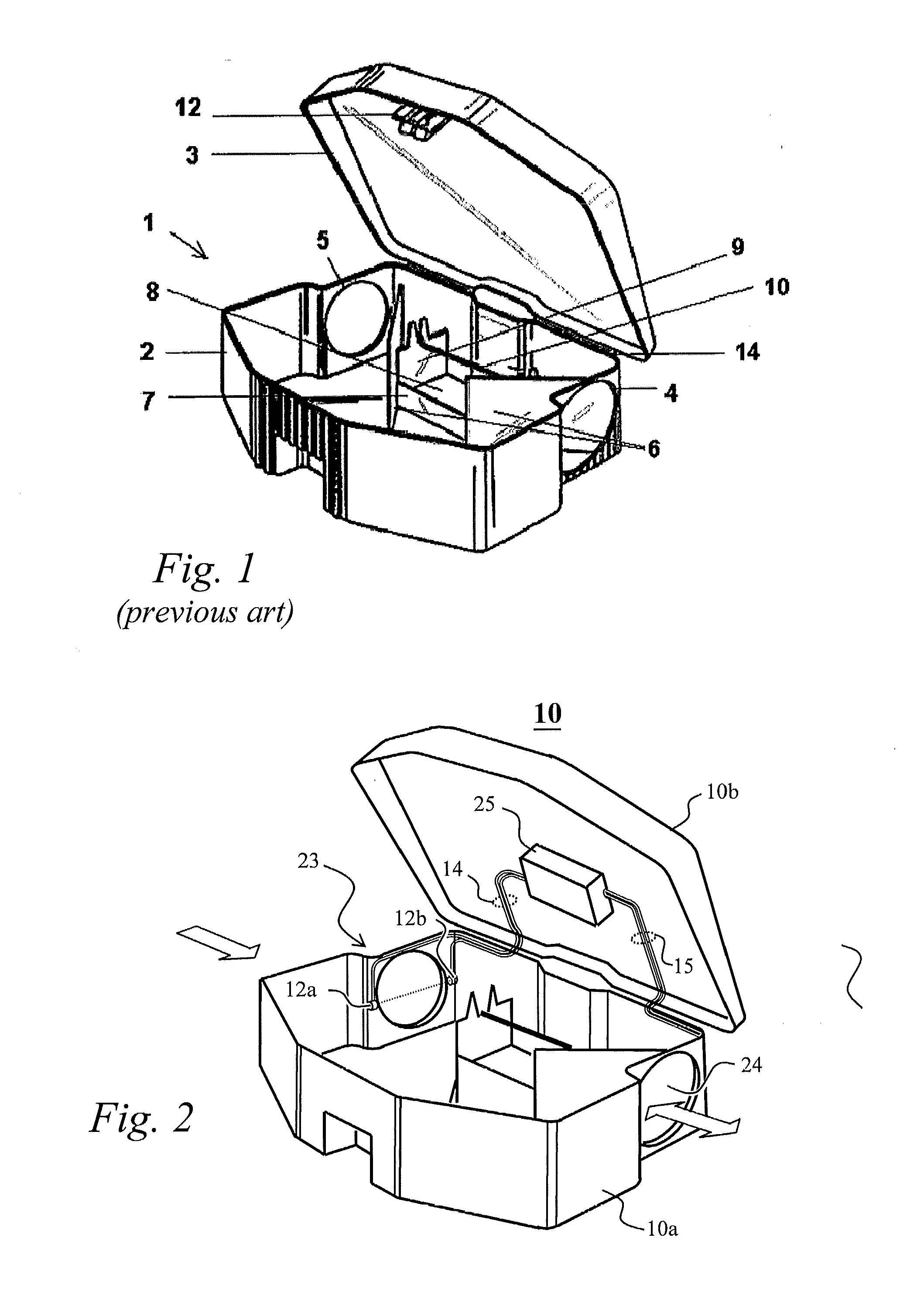
[0052]Referring now to FIGS. 2, 6 and 7, slave unit 10 is set up in a commercially available plastic enclosure consisting of a lower body 10a and a lid 10b. Although the figures show a specific enclosure, any other commercially available case may be used, as long as it is provided with two openings 23 and 24 for entry end exit of the rodent. As shown in FIG. 2, opening 23 is provided with an infrared sensing device comprising an infrared emitting diode 12a and a detector 12b which are connected by a pair of wires 14 to a controlling device 25 fastened to the internal surface of lid 10b. A similar sensing assembly (not shown in the drawing) is placed in opening 24 and is connected to the same controlling device by means of wires 15. A state of the art processor 11 in said controlling device 25 manages the events related to the entry and exit of a rodent through said openings.

[0053]As shown in block diagram of FIG. 7, the electronic components of the slave unit are powered by power su...


PUM


Abstract

The invention comprises a plurality of traps fitted with data processing means, arranged in a given coverage area, said traps comprising specific traps for rodents, specific traps for flying insects and specific traps for crawling insects. The data processing means include animal presence sensors, means for processing the information provided by said sensors and means for communicating said information, as well as power supply means. According to another aspect of the invention the traps in a given area are superintended by a master station that oversees the operation of said "slave" traps, via said information communication means. The aforesaid area superintended by a master station may include different kinds of traps, i.e. a single area may simultaneously contain specific traps for rodents, specific traps for flying insects and specific traps for crawling insects, said traps being identified by codes that indicate the kind of pest the trap is used for.

Description

FIELD OF THE INVENTION[0001]The instant invention refers to the control of pests in urban environments, comprising commercial or industrial buildings as well as warehouses for storing agricultural products, and more specifically to the control and elimination of rodents such as mice and rats as well as flying or crawling insects.DESCRIPTION OF RELATED ART[0002]Infestation by pests such as rats, mice, crawling and flying insects and the like is a problem which has faced humankind for many thousands of years, occurring in dwellings, in commercial and industrial facilities as well as being associated with all aspects of agricultural activities. Besides destroying part of the feedstuffs in the field and in the storage facilities, these animals may act as vectors for diseases affecting humans and cattle. Besides eating grains growing in the field as well as foodstuffs stored in processing facilities, rodents such as rats and mice transmit bubonic plague, leptospirosis and other serious d...

Claims


Application Information

Patent Timeline
Patent Type & Authority Applications(United States)
IPC IPC(8): A01M1/00A01M99/00A01M23/00
CPCA01M23/005A01M25/004A01M31/002A01M1/026A01M99/00A01M1/106A01M1/00A01M23/00A01M1/103
Inventor GALEB, ALEXANDRE
Owner ATTAX DEDETIZACAO DESRATIZACAO S C LTDA ME
Why Eureka
Try Eureka